Hi! I need a voltage divider that I can program by software to obtain subvoltages of my 12V 2A power supply. Is it possible?
Thanks in advance!
Hi! I need a voltage divider that I can program by software to obtain subvoltages of my 12V 2A power supply. Is it possible?
Thanks in advance!
If you connect 12V to an analog input you will kill the input. No amount of software will prevent that. You must reduce the voltage to be no more than Vcc + 0.5V to prevent harm to the input and no more than Vcc to be able to convert the voltage with the ADC with any accuracy (defalut Vref).
Thanks for your reply groundFungus,
I want arduino only controll the amount of voltage in the output of the voltage divider , but the power supply that is connected to a motor driver, is isolated of the arduino circuit. Each circuit has his own power supply.
I believe a DC motor control board will do exactly what you need.
If that does not suit your purposes, then you will need to supply more details on how many voltages you want to supply to the motor.
Hi,
I'm assuming you are considering adding some hardware that can be controlled by software. This being the case;
There are software controlled resistors or perhaps a DAC could work. However you stated the power supply circuits are isolated from the Arduino. This has to be addressed as well. Could you tell us more?
Yes, of course.
I have an EasyDriver to control my stepper motor through arduino. The stepper must carry loads between 1 to 3Kg. I can use a 12V 2A power supply or a 14.4V 2500mAHr battery if I'm out of home.
My purpose is, when stepper must carry light loads, to have an LCD menu where I can set up to supply less voltage to the driver to prolong battery life. As I read, lower voltage produces lower torque in my stepper motor driver.
EasyDriver has a potentiometer, but it only controls current, not voltage, and potentiometer will be put inside a box and will not be accessible.
If the EasyDriver is the one from SparkFun, review the schematic and see if you could substitute a digital potentiometer in place of the 10K rotary. Or Review the datasheet for the chip and see if a DAC could drive the REF pin of the driver chip.
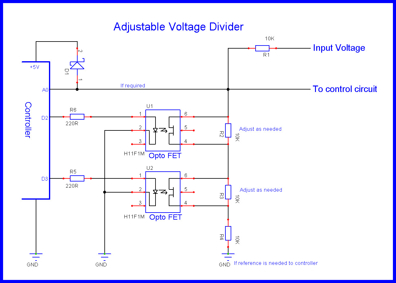
You can use some fixed resistors in the divider which are shorted out with an opto fet.
larryd:
You can use some fixed resistors in the divider which are shorted out with an opto fet.
Can you give me more details about please?
In short, its a way to replace the potentiometer with a series of distinct values.
Determine which voltages you need.
Build a stack of resistor with multiple resistor segments that will produce the voltage you want (total value of resistors should be 10K to mimic the one you are replacing).
Use a opto fet or relay to connect the selected discrete voltage value to the REF pin.
lamartinada:
Yes, of course.I have an EasyDriver to control my stepper motor through arduino. The stepper must carry loads between 1 to 3Kg. I can use a 12V 2A power supply or a 14.4V 2500mAHr battery if I'm out of home.
My purpose is, when stepper must carry light loads, to have an LCD menu where I can set up to supply less voltage to the driver to prolong battery life. As I read, lower voltage produces lower torque in my stepper motor driver.
EasyDriver has a potentiometer, but it only controls current, not voltage, and potentiometer will be put inside a box and will not be accessible.
You cannot reduce the power used by a stepper driver by reducing the supply voltage, it will pull all the power it needs to supply the current requested - you have to control the set current, which cannot be done programmatically on the EasyDriver.
Stepper drivers are power converters, give them more volts and they draw less amps, and vice versa.
Steppers are basically not suitable for battery operation as they consume way more power than other motors - the stepper doesn't really notice the load in fact, its pulling full current with no load.
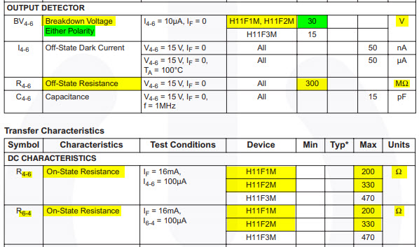
https://www.fairchildsemi.com/datasheets/H1/H11F3M.pdf
H11F2M or H11F1M are rated at +-30V
EDIT
Updated schematic
Might want to use H11F2M or H11F1M which are rated at +-30V
Ok. I try it. It seems a good solution.
Thanks for all ![]()
Any system you use except by switching between separate efficient power supplies at different voltages will involve interposing a resistance of some sort between the power supply and your motor.
1/ below a certain value of voltage your motor won't work at all.
2/ the resistance will itself dissipate power, and so won't save much overall power.
so
don't do it.
unless you interpose eg an efficient voltage controllable buck convertor. and you will have to know the load before you choose the voltage unless you detect motor movement.
This isn't quite trivial. Unless desperate I wouldn't bother.
Electric bikes, buggies etc use a detector of motor position via usually hall effect sensors on their 3-phase motors, to choose the coils to drive, and adjust the power by PWM of their driver waveforms . I'm not sure how you'd achieve this with a standard stepper motor - which doesn't give you feedback of it's position - but it might be possible.
Not trivial.
But for your application a BLDC motor might be a better approach.
Allan
lamartinada:
Hi! I need a voltage divider that I can program by software to obtain subvoltages of my 12V 2A power supply. Is it possible?Thanks in advance!
If the output terminal (connected to a load) needs to be a constant voltage, then everything should be ok if the load draws very little current (when compared with the source current).
But if you need an output voltage where output current is a significant amount, then you'd need to focus on a programmable variable voltage power supply.