How to make Wall lights to work with both wall switches and arduino's relay

Hi guys,

Ι will renovate my house and I will make new wire connections for my house's lights. What I want to do is to have 2 switches for each light (3-Way Switch connection) as well as the ability arduino to detect in which state lights are and turn on or off the lights with a relay.

Also I would like to clarify that I want lights to have the ability to be handled independently of arduino.
So if arduino has an issue, I will have the ability to open or close the lights.

One idea is a 4-Way Switch connection (2 switches and as 3rd switch will be the arduino's relay).
But how can arduino detect if the light is on or off ?

Can someone please help me ?
Sorry for my bad English.

Chipakias:
One idea is a 4-Way Switch connection (2 switches and as 3rd switch will be the arduino's relay).

That doesn't make sense in any language. If you want to operate one light(s) with three switches, you will need two normal SPDT switches, which are wired as for a two way setup, and one DPDT switch in the middle of the circuit. I don't suppose it matters which one is actually a relay. Any additional switches would also be DPDT.

There are 3-way home automation switches/dimmers. [u]Here is an X-10 version[/u].

Usually one switch is the master switch that actually controls the light, and and the other switch is a transmitter/controller so, you can have multiple transmitter switches and/or control the light with any of you other home automation controllers/timers. (It's wired differently from a regular 3-way switch). There are ways to convert a single-switch to a 3-way without re-wiring, and I've seen battery-operated transmitter-switches. (I have a wireless battery-operated remote controller like [u]this[/u].)

as well as the ability arduino to detect in which state lights are and turn on or off the lights with a relay.

I'm not sure if you can find that feature. X-10 is one-way communication, but there may be another protocol that can read the state of the light. But, that may not be necessary... Rather than checking to see if the light is on or off, you can simply send an on or off command.

You can build a home automation controller with the Arduino if you want, but I recommend that you buy the wall switches and design your Arduino controller around one of the existing home automation standards.

as well as the ability arduino to detect in which state lights are and turn on or off the lights with a relay.

It's a little difficult to sense when the light is electrically ON. Basically an Optoisolator at the place in the wiring where the light power changes.

But it easy to sense whether it is light or dark in some appropriate way; just a light-dependent resistor. Run it to an Arduino analog input and you can tune up what is detected as light or dark. Then if you want to change from light-dark-light you just have the arduino change a relay state.

Make sure you understand "3-way" and "4-way" See THIS:

To be in the "4-way" part of the circuit, you need a double-pole-double-throw relay. OR, much cheaper and easier is a 2-relay board like THIS: You can locate it near the power wiring and it can be optically isolated from the Arduino.

DISCLAIMER: Mentioned stuff from my own shop...

If you really want to "independent of Arduino" way you could indeed use 1 relay as extra switch. To detect the state of the light you could use a opto coupler connected to the light (ac opto or a dc opto with bridge rectifier). Instead of a resistor you could use a capacitive dropper aka a capacitor. This draws less current / less heat (but has a low power factor but who cares in domestic use...) It would make a small small and device but you need to make a PCB. A very KISS solution is to grab a USB charger and connect it parallel to the light and feed the output to the Arduino (via a +- 500k resistor to not phantom power the Arduino by accident).

But keep in mind, if you use a standard relay (mono stable) and the Arduino fucks up and changes the output to the relay (for example a reset) the whole 3-way switch changes so it might turn the light on.

But depending on what you want I would not really bother with the "independent of Arduino" part and just route the switches to the Arduino and make them switch low voltage. (Each individual, common if you use push buttons or a low voltage 3-way switch). Just bug check the program good. Worst thing that can happen is the light wouldn't turn on/off. The direct and the "independent of Arduino" way can both create a great disco when there is a bug :smiley: You don't fix that with the 3-way switch with relay method.

Using the 4-way switch diagram in TerryKing's link (thank you for that, btw), it looks like the simplest way to achieve your goal would be to use your Arduino's relay in place of the 3-way switch connected to the light:

There are several ways to detect if there are 120Vrms between neutral and the common pin of the 3-way switch, the easiest of which would be to use an optocoupler as shown on page 59 of this link -> http://docs.avagotech.com/docs/AV02-4387EN

Chipakias:
Also I would like to clarify that I want lights to have the ability to be handled independently of arduino.
So if arduino has an issue, I will have the ability to open or close the lights.

This nonsense seems to crop up every time for the exact same frequent request.

The Arduino does not "have an issue". It will be as reliable as any other part of your system if you design it correctly (including watchdog).

The simplest and most reliable approach is to have the Arduino control the light directly via a single relay. Simple buttons (or touch panels) at each station can then command the Arduino to toggle or set the light.

I don't see a need for any micro or relays. Standard 2 or more way switching using c/o switches and intermediate switches would suffice.

bluejets:
I don't see a need for any micro or relays.

Indeed. It is notable that everybody is talking but the OP. There may be a good reason to use Arduino but there is no evidence so far. Rather than what I said before, I think this is a either a job where Arduino does it all, as Paul suggests, or as you suggest, it's all done with switches, and I guess Arduino gets employed to do something more useful.

Being able to turn on/off the light with switches and with the Arduino is a totally valid thing... What he want to do with the Arduino isn't important. Maybe he wants to turn it on when it's dark, between 8 and 12 of he just want to stobe the light, who knows. All that counts is that he wants to control the light via switches and the Arduino.

But I would say, go for an all Arduino solution. Push buttons would be the easiest solution because it only tales 2 wires and you can parallel as many buttons as you want. The whole independent of Arduino part is a bit overrated. If you do it in the 3-way switch way and your code starts to toggle the relay constantly for no reason then yeah, you can counter act with the switches but you still end up with a disco...

Paul__B:
The simplest and most reliable approach is to have the Arduino control the light directly via a single relay. Simple buttons (or touch panels) at each station can then command the Arduino to toggle or set the light.

what would be simple is to use a double throw, center off, spring return, momentary light switch.
you lift up, the lights go on, number of switches would be relevant.
the one relay that controls power to the light would be energized upon a signal. if you use a DPD, you can feed power to the coil through the NO of one pole.
you change state by powering the coil with the switch.
the relay changes state, the first pole energizes the light.
the second pole energizes the coil to hold the coil
your light switch opens that loop, power to the coil is lost, circuit opens, light goes out.
you can have dozens of switches and the Arduino could be but one of them.
one relay to find them, one relay to bind them, and out of the darkness bring light.
one part, no other electronics needed. but, 4 wires.

Guys,
First of all thank you for the great support!
I know that easiest solution would be lights to be turned on or off from one relay and momentary buttons to drive arduino.
But !
I want lights to work independently arduino. So if arduino has any issue, the house has to work normally with the common switches.

Also I understand the risk of disco in case power goes down and up but in case I supply arduino with power from a battery (like alarms/pc ups) I believe that this problem is solved.

But what I want is that, even when I am absent from the house, to know if I have left any light on. (Also to control it).

This is why I what to know the state of lights.

Septillion said that I could use USB charger and connect it parallel to the light. This is a good idea but I am afraid that these things have certain time of life as it is very usual to be broken as well as they would consume power all they time lights are on.

Also Septillion said:

To detect the state of the light you could use a opto coupler connected to the light (ac opto or a dc opto with bridge rectifier). Instead of a resistor you could use a capacitive dropper aka a capacitor. This draws less current / less heat (but has a low power factor but who cares in domestic use...)

Septllion do you have a diagram or an example in order to understand how this works ?

If you use one relay that is controlled by teh Arduino, you ahve one 3-way switch. then, you have all 4-way switches in the rest of the house, and of course, one other 3 way on the other end to complete the loop.

now, all you need to do is to know if there is current on the line.
there are a few ways, some invasive, some non-invasive.

a CT or current transformer
http://www.ebay.com/itm/141689383548
could be put on one end of the line and monitor, by aid of the Arduino. if power is being used.

I would offer that the EXP with wifi would be better than an Arduino.

@dave-in-nj Why do you want to know it there is current? You want to know if there is voltage. If the light is broken you have no current but the system switched right. If you poll for current all the time to know is the light really turned on and act on that all the time then the relay will just start bouncing... Testing for voltage is just way easier...

And what's a EXP?

Chipakias:
Also I understand the risk of disco in case power goes down and up but in case I supply arduino with power from a battery (like alarms/pc ups) I believe that this problem is solved.

No no no no, it has nothing to do with power going down. Because if power is down (except for when the Arduino power supply blows but that should be wayy rarer then a blown light bulb...) then of course the light can't turn on as well. But if the power is back then the Arduino just starts and you're good to go :slight_smile:

The problem you have is two sided
a) The Arduino doesn't make errors, if does exactly what you tell it to do. So if there is a error it's because of you wrote it (or used code that has errors..).
b) The error you create doesn't need to be that you can't switch the light aka a unresponsive Arduino. The error you make can just as good be that the Arduino always counter acts on you switch acting (because, he, it can sens the light being on) or some other weird thing that (randomly) turns on and off the relay.

Yeay, you can still control the light with a switch then but so can the Arduino, you don't overrule it. And if you control the light but the Arduino does so as well but in a way you don't want, then the fact you can turn on/off the light is useless. The Arduino will still do what it thinks it need to do, maybe create a disco, maybe turn off the light when you turn it on etc. It can still act so there is nothing independent about it.

The only fail safe "solution" would be to place another switch parallel with the Arduino controlled switch (or chain of switches). But that would not be very home automation-ish.

Conclusion, just write good code and do bug testing on it before you use it in a real situation.

there are always choices.

as I see from what the OP is saying, is that the system needs to work with or without the Arduino.
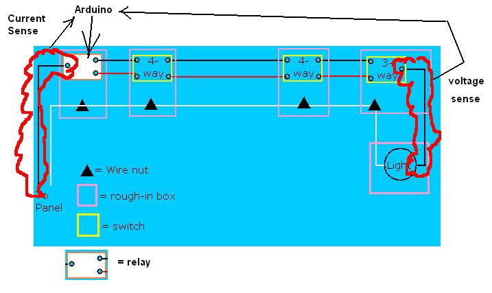
that he wants to use toggle, lever action switches, 3-way or 4-way, and is fine with running 3 wire for the circuit.

what I was getting at was that if you put a bank or relays in the home automation panel, you have a starting point that is both accessible and conveniently located.

in order to measure if the light is lit, you have many choices. a light sensor. a heat sensor, a voltage sensor and a current sensor.

light and heat are only present at the lamp itself.
voltage is present at all times on some wires, which wires depends on the state of the switches, and only the wire to the lamp will have voltage when the lamp has power. ergo, the only valid place to measure voltage is at the lamp.
since you have a central panel, you have a single common power wire. if the lamp is lit, there is current. if the lamp is not lit, there is no current. there is always voltage.

it is my belief that a choice between running a wire from each lamp back to a panel is more difficult that testing for power at the main panel. I also believe that since the OP does not trust in automation, that having the central location makes troubleshooting easier.

sorry for the short-hand. ESP. there is a board with an ESP8266 chip that is a drop in replacement for the UNO, but with only 1 analog pin. but it has built-in WiFi it can do all the logic and sensing and control, but handles the WiFi bit

http://www.aliexpress.com/
search for espduino

I always say application-application-application
the choice of a local current transformer vs running a wire across the house back to the panel
or locating the Arduino in the wall next to a light switch in the room that the light is in.

I would try to make the case that having an Arduino in every room, one for each light would be difficult, but in all honesty, I like modular and single device controls.

although, one Arduino could control all the lights in the house.

TIPS :
if you are doing a whole house, put in a relay on the light above the stove. most stoves today has an indicator when they are hot.

bathroom fan, add a humidity sensor to turn it on and off

provide a CT on the washer and dryer as well. can text your phone when done.

The ESP8266 I know of course. But you wrote EXP :wink: But if you need the Uno format for a permanent installation, mehhh.

If we talk full home automatic then yeah, things change... But I would hate to have one central relay board for a house. Then you need way to many wires. Especially when you run useless double wires for a multi way switch with a relay in it. Multiple decentralized boxes would be easier in my opinion. So the whole centralized box thing is a assumption.

If we talk full house automation / control for all/multiple lights then the whole project changes. Then it becomes wayyyy bigger. Then "just a ESP/Arduino" does not cut the mustard...

The "remote control" aspect was indeed new. How are you planning on doing that? Thought about security?

But the whole multi way switch thing because it's "safer" is rubbish. If you can't really overwrite the action of the Arduino then you can't say you solve Arduino failing situations that way. You're code failing in a way that the Arduino switches when you don't want it to is just as common/easy to do as a not responding Arduino. And both are just bugs, if they happen just debug the code and try again. There are worst things then a light not turning on or disco lights. But you're solution isn't a solution.

a bit more about choices :
local voltage sensor has to have a circuit tied into the mains voltage. that means either there is a direct line, albeit with resistors, or an opto.

if the control is remote, then that wire has to run to the control.. choices, choices.

if you add a board with an opto, and resistors and such. you add complexity.

The goal of not using the Arduino as the master forces some of these choices.

septillion:
The ESP8266 I know of course. But you wrote EXP :wink: But if you need the Uno format for a permanent installation, mehhh.

If we talk full home automatic then yeah, things change... But I would hate to have one central relay board for a house. Then you need way to many wires. Especially when you run useless double wires for a multi way switch with a relay in it. Multiple decentralized boxes would be easier in my opinion. So the whole centralized box thing is a assumption.

If we talk full house automation / control for all/multiple lights then the whole project changes. Then it becomes wayyyy bigger. Then "just a ESP/Arduino" does not cut the mustard...

The "remote control" aspect was indeed new. How are you planning on doing that? Thought about security?

But the whole multi way switch thing because it's "safer" is rubbish. If you can't really overwrite the action of the Arduino then you can't say you solve Arduino failing situations that way. You're code failing in a way that the Arduino switches when you don't want it to is just as common/easy to do as a not responding Arduino. And both are just bugs, if they happen just debug the code and try again. There are worst things then a light not turning on or disco lights. But you're solution isn't a solution.

esp.. exp... yup. that is my bad. My speak cheaker turns on for a second, then turns off by the time I am done with a paragraph.
I am 100% with you on most of the HomeAutomation. good choices if you use automation as the base and build up.
with this overlay and the no-interference rule, that adds some complexity.
modular is great for retrofitting an old home, use existing wires. smart, convenient, simple.
the no fail approach does mean more work on the installation. but more reliable if you have a meltdown.
security ? if it is good enough for the Secretary of State and the US Federal Gov't, then it is enough security for me !

But there is no fail safe. The only fail safe way to turn the light on would be a seperate parallel switch. The only fail save way to turn the light off would be a extra switch in front (so not in) the multi way switches chain. But that's not very home automation-ish to have extra fail safe switches in your house.

So the closest option is to just write proper code. Use Watchdog if you want. The whole relay based multi way switch just gives you more wiring but no fail safe.

And about which Secretary of State and the US Federal Gov't security are we talking about? Are the security less? :smiley:

here is a very real senario :

a EMP goes off and wipes out all electronical things.
your hydroelectric generator offers power for those calm days your wind mill does not.

your house is dark because every electronical bit is fried.
Chipaklas walks in and flips the switch by the door and the iights come on.

Home automation does not have to interfere or block access to any parts of your life.
if you rely on every part working and the smallest failure crashes your whole system, something as simple as a power supply failure. you loose the ability to turn your lights off from the car, but your life goes on without any inconvenience or interruption.

The OP was very clear, any automation was to work with and not block or work instead of, the mechanical system.

as for so-called security, read any of the thousands of available e-mails on the internet from hackers. the only people who do not know about them are the media in the US. If hackers can penetrate the most secure server on the planet, then I have no expectations that some hacker will not turn my lights off at the most inopportune time.