Dear Paul, Currently I'm applying sine wave using laser light with 2KHz frequency. and trying to measure the same frequency on the output without any change. The change in input frequency or change in reflective body will cause to change the frequency and I will measure it.
Sorry to break your bubble, but you are AMPLITUDE modulating the laser, not frequency modulating it.
The 2 kHz amplitude modulation won't change. A single LED outputs a very wide range of frequencies, so you have no chance at all of measuring a change in that. Here are the emission spectra (wavelengths) for typical visible LEDs.

Im controlling the laser by signal generator and I measured the output frequency using oscilloscope (I will show the experimental setup tomorrow) . Im generating a sine wave having Frequency = 2KHz, Amplitude = 5VPP, DCShift = 1.8VPP
Can you supply documentation showing anyone able to frequency modulate a laser? That would entail changing the light emitting diode structure.
What laser? Is this statement from your first post not correct?
I'm trying to measure the frequency and wavelength of the Red LED of MAX30102
Dear @jremington I will use only RED LED or May be IR LED and will supply a constant signal and photodetector of MAX30102 will measure and give output frequency/ either same or shifted does not matter, Im interested just to capture it
I have 3 options Laser/RED/IR. But the objective is same to capture using MAX30102
You seem to be very confused about the difference between the frequency of the light emitted by an LED (which is actually very broad range of frequencies) and the frequency of the amplitude modulation of that light.
Come back to the forum when you understand that difference, and rephrase your question.
@jremington Dear, I dont have problem with the light source. Im interested to measure the frquency of the light being used. My project is based on the doppler effect (where I will use light to shine the object and will measure the frequency after reflection from that object using photodiode). For this Im using MAX30102 sensor.
Use a laboratory grade spectrometer to measure the very broad range of frequencies produced by the LED. The result will look like one of the peaks in the plot posted in #23.
There is no chance at all that you could measure the Doppler shift in frequency of light from a moving LED.
There are details on how to make a spectrometer (reasonably accurate and simple) on the web.
Use a fluro light to calibrate.
I use mine to check the frequency of LED epoxy cure.

There is no technical information in that advertisement.
If you believe a word of it, write to the authors and ask for the technical details, rather than asking on the Arduino forum.
@engr_khalil, so I'll play along. One of the references in the paper you cited has this graph showing doppler shift vs velocity.
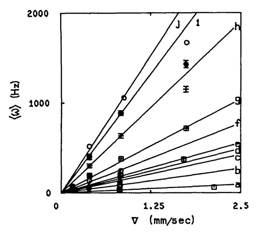
So using the formula from one of the posts above:

... and assuming 1500nm IR light (200 THz) and velocity being measured of 1.25 mm/s (0.00125 m/s) from the graph, I get a doppler frequency shift of 833 Hz. Which surprisingly lies on that graph ![]()
So, this tells me 4 things:
-
It's the doppler shift of the optical frequency that's being measured (not the modulating frequency).
-
It's being done with IR light.
-
It requires optical mixing to get an IF signal at the dopplershift frequency. There's zero chance of doing that with an LED, you need a laser diode.
-
I'm extremely doubtful that you'll be able to pull this off.
BTW, that's just to get a raw signal. That referenced paper also reveals there's extensive math required to pull anything useful out of the noise and statistical variation that's swamping the signal.
@gfvalvo you refer of course to the 1981 paper (reference 4 of the advertisement), which used an extremely narrow band HeNe laser in a model system, full text at: Optica Publishing Group
Here is the caption to Figure 8, which you posted. This is a far cry from the claim of measuring stuff through a finger, using a laser diode as the light source. While this may in fact be possible, I see no compelling reason to believe a single word of the advertisement. Note all the graphs with no scale marks on the axes!
Fig. 8 Mean Doppler shift 〈ω〉, as defined in Eq. (32), plotted vs mean velocity for a variety of particle sizes and volume fractions of fluid moving through the hollow fibers of the model system. In the 0–2-mm/sec range, the mean frequency 〈ω〉 increases linearly with mean particle velocity. A monotonically increasing dependence on particle density and decreasing dependence on particle radius are also observed, a–g, human blood diluted to hematocrits of 0.003, 0.006, 0.012, 0.012, 0.025, 0.035, 0.050, and 0.12, respectively; h–i, 0.55-μm radius PSL spheres at concentrations of 0.5 and 1.0 % v/v; j, 0.264-μm radius PSL spheres, 1 % v/v.
Well, that's the difference between engineering and physics ![]()
![]()
![]()
I was merely establishing the parameter space.
Dear @jremington my question was related to arduino programming using the MAX30102 sensor not related to the experimental setup.
A spectrometer is used to measure the frequencies/wavelengths emitted by an LED, not an Arduino with a MAX30102.
again you are referring to the experimental setup. this is not the question at all.