Hello. I want to ask, can arduino measure the voltage output from 555 timer(astable)
So you want to measure the output voltage, not the frequency?
The top voltage is always constant. ~1.7volt (LM555) less than the 555's supply.
If you tell us what you want to do, we might give better advice.
Leo..
A 555 has two voltage outputs, a digital one and an analogue one from the capacitor. Which one do you want?
What frequency is it going at?
In Astable operation, the output is a pulse stream.
You could low-pass filter that output with a 4.7K resistor and 10uF cap, will get a pretty DC-ish output that you could read with analogRead as long as the output stayed below 5V.
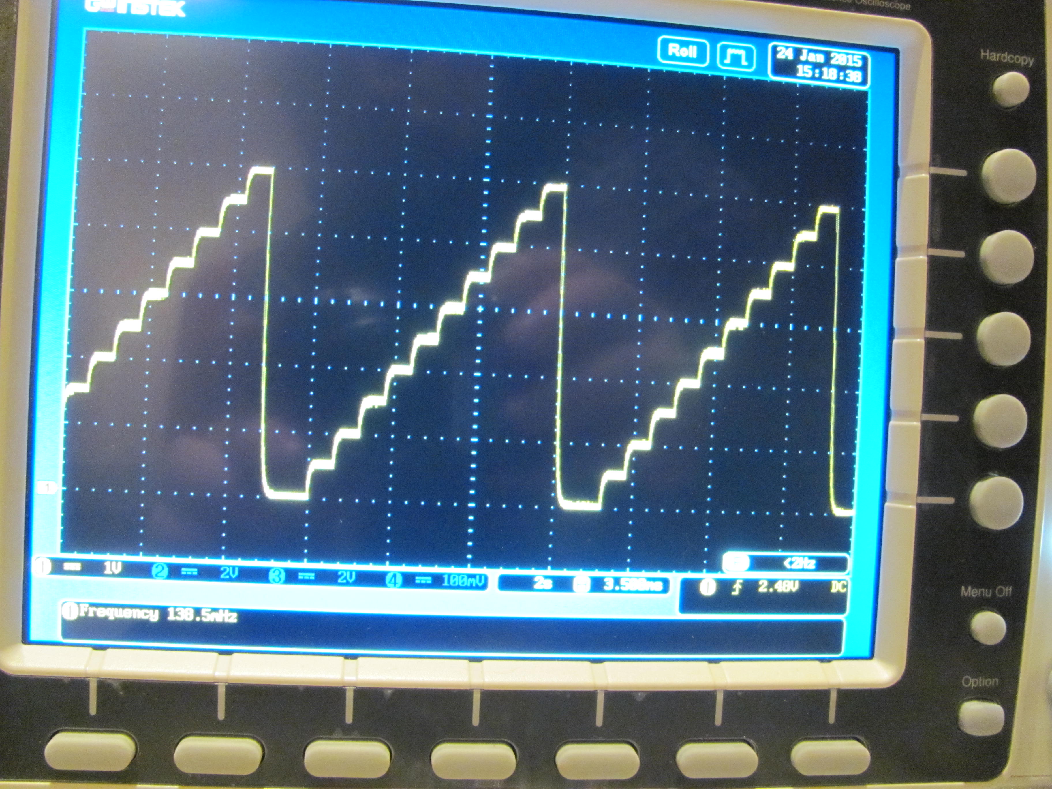
Here's the filtered output from analogWrite() with values of 0, 25,50,75,100,125,150,175,200,225,250 every so many mS.
http://sim.okawa-denshi.jp/en/CRlowkeisan.htm
You also use pulseIn() and read the high pulse level and the low pulse level for a more direct measurement, again with the output no more than 5V.
Hello. I want to ask, can arduino measure the voltage output from 555 timer(astable)
As already pointed out, your question doesn't exactly make sense, in view of the fact that the whole purpose of a 555 astable is to generate a clock frequency, or a reference frequency, or some form of 50% duty cycle squarewave. The duty cycle can be varied but almost all 555 astables are intended to be
squarewaves. That being the case, it is evident , from the inherent design of the 555 , that the output is going to be an alternating HIGH/LOW with LOW being 0V and HIGH being the Vcc voltage of the 555. If you were to use 5V for the Vcc, then it would be a 5V squarewave . If you ran the 555 off a 9V PP3 battery and used an equal value (10k/10k) voltage divider on the output, then you could derive a 4.5V square wave.
As already mentioned , you could use PulseIn
but this is only going to tell you the pulse width. Without a scope, you would not know if it is a 50% duty cycle because you wouldn't know the period. You would need to measure the period (using an arduino) and then you could calculate the frequency. (P= 1/f)
Or, you could use Nick Gammon's Frequency Counter sketch:
 // Timer and Counter example
// Author: Nick Gammon
// Date: 17th January 2012

// Input: Pin D5

// these are checked for in the main program
volatile unsigned long timerCounts;
volatile boolean counterReady;

// internal to counting routine
unsigned long overflowCount;
unsigned int timerTicks;
unsigned int timerPeriod;

void startCounting (unsigned int ms)
  {
  counterReady = false;         // time not up yet
  timerPeriod = ms;             // how many 1 mS counts to do
  timerTicks = 0;               // reset interrupt counter
  overflowCount = 0;            // no overflows yet

  // reset Timer 1 and Timer 2
  TCCR1A = 0;
  TCCR1B = 0;
  TCCR2A = 0;
  TCCR2B = 0;

  // Timer 1 - counts events on pin D5
  TIMSK1 = bit (TOIE1);   // interrupt on Timer 1 overflow

  // Timer 2 - gives us our 1 mS counting interval
  // 16 MHz clock (62.5 nS per tick) - prescaled by 128
  //  counter increments every 8 µS.
  // So we count 125 of them, giving exactly 1000 µS (1 mS)
  TCCR2A = bit (WGM21) ;   // CTC mode
  OCR2A  = 124;            // count up to 125  (zero relative!!!!)

  // Timer 2 - interrupt on match (ie. every 1 mS)
  TIMSK2 = bit (OCIE2A);   // enable Timer2 Interrupt

  TCNT1 = 0;      // Both counters to zero
  TCNT2 = 0;

  // Reset prescalers
  GTCCR = bit (PSRASY);        // reset prescaler now
  // start Timer 2
  TCCR2B =  bit (CS20) | bit (CS22) ;  // prescaler of 128
  // start Timer 1
  // External clock source on T1 pin (D5). Clock on rising edge.
  TCCR1B =  bit (CS10) | bit (CS11) | bit (CS12);
  }  // end of startCounting

ISR (TIMER1_OVF_vect)
  {
  ++overflowCount;               // count number of Counter1 overflows
  }  // end of TIMER1_OVF_vect


//******************************************************************
//  Timer2 Interrupt Service is invoked by hardware Timer 2 every 1ms = 1000 Hz
//  16Mhz / 128 / 125 = 1000 Hz

ISR (TIMER2_COMPA_vect)
  {
  // grab counter value before it changes any more
  unsigned int timer1CounterValue;
  timer1CounterValue = TCNT1;  // see datasheet, page 117 (accessing 16-bit registers)
  unsigned long overflowCopy = overflowCount;

  // see if we have reached timing period
  if (++timerTicks < timerPeriod)
    return;  // not yet

  // if just missed an overflow
  if ((TIFR1 & bit (TOV1)) && timer1CounterValue < 256)
    overflowCopy++;

  // end of gate time, measurement ready

  TCCR1A = 0;    // stop timer 1
  TCCR1B = 0;

  TCCR2A = 0;    // stop timer 2
  TCCR2B = 0;

  TIMSK1 = 0;    // disable Timer1 Interrupt
  TIMSK2 = 0;    // disable Timer2 Interrupt

  // calculate total count
  timerCounts = (overflowCopy << 16) + timer1CounterValue;  // each overflow is 65536 more
  counterReady = true;              // set global flag for end count period
  }  // end of TIMER2_COMPA_vect

void setup ()
  {
  Serial.begin(115200);
  Serial.println("Frequency Counter");
  } // end of setup

void loop ()
  {
  // stop Timer 0 interrupts from throwing the count out
  byte oldTCCR0A = TCCR0A;
  byte oldTCCR0B = TCCR0B;
  TCCR0A = 0;    // stop timer 0
  TCCR0B = 0;

  startCounting (500);  // how many mS to count for

  while (!counterReady)
     { }  // loop until count over

  // adjust counts by counting interval to give frequency in Hz
  float frq = (timerCounts *  1000.0) / timerPeriod;

  Serial.print ("Frequency: ");
  Serial.print ((unsigned long) frq);
  Serial.println (" Hz.");

  // restart timer 0
  TCCR0A = oldTCCR0A;
  TCCR0B = oldTCCR0B;

  // let serial stuff finish
  delay(200);
  }   // end of loop
It is quite unlikely you actually want to measure the charging voltage, but as stated, you could do that with an analog input.
raschemmel:
It is quite unlikely you actually want to measure the charging voltage, but as stated, you could do that with an analog input.
You would of course need an op-amp buffer.