Please provide support; I am currently using an Arduino Pro Mini 3.3V. The Arduino is powered by a 18650 battery at 4.2V. I have connected an L80 GPS module to the Arduino. Everything is working, and there is communication, and the position is displayed. Unfortunately, I don't know how to temporarily turn off the power to the L80. The L80 has two pins—one VCC (main power supply) and a BCK_VCC pin (the backup power supply for the clock). I tried using a MOSFET (2N7000) to control the power: I connected the drain to the battery power, the gate to pin D7 for control from the Arduino, and the source to VCC of the L80, but unfortunately, the circuit doesn't work. Can someone indicate how to do this correctly?
I would like to point out that I have the power connected to VCC_BCK, and it must be connected here. The GND is also connected to the L80.
Dear all, dear srnet, I really, really thank you for the support and the diagram. I have one more question – will this diagram be energy-consuming?
According to my preliminary calculations, if the system activates every 2 minutes for 5 seconds, it will draw around 1 mA (the current consumption of the L80 is around 30 mA) and 3.3V arduino.
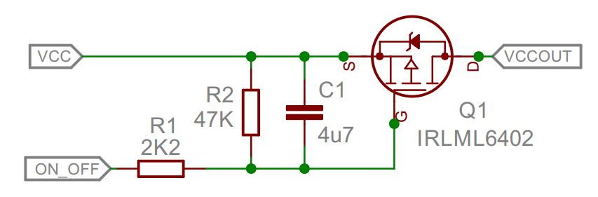
Of course, when ON_OFF is low current will flow through R1 and R2.
Dont assume that a GPS in hot fix mode will always get a fix in 5 seconds, it might mostly do that, but then sometimes it can take 10, 15, 20 seconds or more.
Hi, thank You for Your solution. I ready did this with P mosfet and it worsk but I've decided to connect just only mosfet without R1, R2, C1. Why this elements are required for?
Without them, there can be quite a sharp current\voltage spike on the Arduinos power rails when the GPS is turned on, which can cause the brownout detector to trigger a reset.
Thank You srnet for fat replay. After longer pause - I did all schemes except capacitor and resistor and You are right the arduino is self restarting - waiting for the rest of parts and let You know about results.
Hi, Can I use analog pin from arduino to control IRLML6402 (for example pin A2)?. Can I use IRLML6402 for acc current cut for humidity and temp sensors?
I have connected two IRLML6402 MOSFETs to an Arduino Pro Mini—one to digital pin 11 and the other to analog pin A2.
The first MOSFET is connected to a Quectel module, and when its gate is high, there is no current on the drain, which seems expected. The second MOSFET is not yet connected to any sensor, but when its gate is high, I notice a small voltage on the drain (0.3V to 0.7V).
Is this normal behavior, or could there be an issue with my circuit?
I swapped the MOSFETs between positions, as well as the capacitor and resistor, but unfortunately, there was no change. In the drawing, I included how it looks in terms of voltage.
update: I connected second mosfet (D) with additional quectel l80 gps module and voltage now is 0v but after sensor connection SHTC3 the voltage on D is 0.3v-0.7v
That's the beauty of your finding, you expect 0 V and instead there's mV present there. Since a Gate have a capacitor between both Drain and Source, this capacitor will be charged up as soon as there's a path from Drain (in this case) to GND, and what's the path when you connect the multimeter?