I have sucessfully used the IRL540N mosfet transistor connected to the arduino to control both DC motors and LEDs and it has been working ok, but I would like to learn a bit more about how mosfet transistors work and behave.
I know that the highly capacitive load they present is not optimal to drive directly from a microcontroller and sometimes it would also be preferable to separate the ground plane of the controller from the load so I have looked a bit at the Avago HCPL-3180-000E that is an 2.5A Gate Drive Optocoupler.
There are a ton of mosfet transistors that will work well, but I have decided on the IRF AUIRFB8407. Main reasons for this is the low ON-resistance and the value for "Total Gate Charge" which I assume has something to do with the energy required to switch from "off" to "on".
The PWM frequency is fairly low (490Hz to 1kHz) compared to most examples in the datasheet that are mostly measured at 1MHz and I assume this also makes it a bit easier to choose the right components.
The thing I would really appreciate some help with is determining the value of the gate resistor in order to get fast switching and no ringing. Normally I use non or low inductive film-resistors and since this is a kind of pulse application I think that might be preferable, but is it perhaps better to have a wire wound, somewhat inductive resistor instead? I assume it will lower the rise time, but probably lower the switching load on the mosfet driver. It should be kept at 2A max.
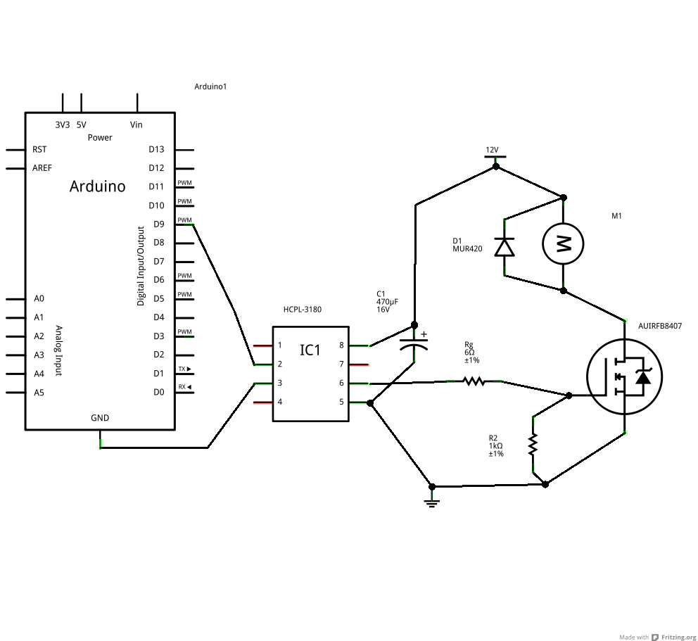
I have done an attempt to draw a crude schematic in Fritzing. It's not pretty but I hope you get the idea.
You don't need a gate resistor unless running several MOSFETs from the same driver,
in which case you use them to damp down any tendancy for differential mode oscillations.
However the gate resistance controls the speed of switching (fast means less loss, but
more EMI, and vice-versa).
2.5A is a lot, add 10 to 30 ohm gate resistor if you want.
The total gate charge is the charge needed to switch the gate from 0V to fully on (normally
10V). Divide it by the driver current to get an idea of the swtiching time. The gate
charge depends on the main circuit current, and is usually quoted for half the maximum
current rating (which is plenty).
That device has 150nC of gate charge, 2.5A means switching time of 60ns (ie as fast as it
can switch anyway).
You need lots of decoupling on the gate driver since it will be switching amps in a few ns,
so 1uF + 22uF ceramic or similar is probably a starting point. These decoupling caps should
be right on the relevant device pins. Some more gate resistance will lessen the strain on these
decoupling caps, note.
But do you actually need opto-coupled gate drivers? You'll need floating supplies for your
high-side MOSFETs which is a pain and expensive. High voltage bootstrapped high-low drivers
are a cheaper approach and available upto 600V working voltage.
Of course if mains is involved then obviously opto-couplers are a requirement.
My plan was to use extremely low ESR caps directly on supply pins of the driver. I am aware of the large currents there.
No for this project I do not need and opto-coupled gate driver, but I figured is was the easiest way to separate the switching load from the arduino.
I do not understand the paragraph about the floating supplies for the high side mosfets. I thought I only needed the low side N channel mosfet if I wanted to PWM control the dc motor. And since this application only use low voltage I thought I could use the same 10-12V supply to power both the mosfet driver as well as the motor and mosfet itself. Is this not a good idea?
The main circuit current is unknown and I would like to try out different motors to see how they behave but I doubt I will ever go beyond 3A. However I believe the starting current of even a small motor will be many times of the running current and I always try to build much more "powerful" circuits than I actually need. It's a good way to learn and if I should ever need to scale things up a bit, I have already made much of the work.
kamelryttarn:
No for this project I do not need and opto-coupled gate driver, but I figured is was the easiest way to separate the switching load from the arduino.
If you have high-side switches (as in an H-bridge), opto isolation means you'll need isolated floating 12V supplies
for each high side FET - not simple or cheap.
Standard MOSFET drivers are usually simplest. Save opto for high voltage / mains where safety is
an issue.
They look pretty similar to me. All are available in pin compatible PDIP-package that makes it easy to try them and also I realized that a very large ceramic SMD cap can be mounted on the bottom side of a PCB directly to the Vdd-pins making the distance between the cap and actual driver ridiculously short.
The 1407 is the cheapest among the three but still provides a continuous current of 1.3 A minimum.