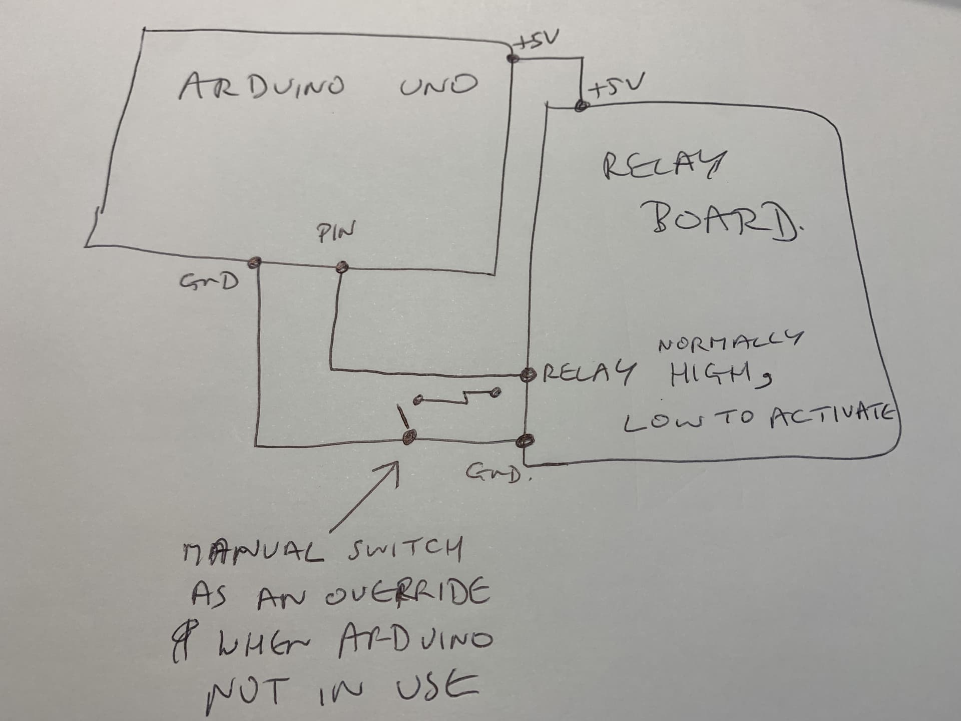
I an using an arduino with a typical relay board which needs to be pulled LOW to activate the relay, so is normally at HIGH
I would like to have a manual override switch that pulls the relay input to ground and I know I could use an input pin for that but I would prefer to have manual operation available at all times)
Is there a simple way to protect the output pin so that it stays at HIGH while I am pulling the relay LOW (momentarily - it's for points motors on a model railway)
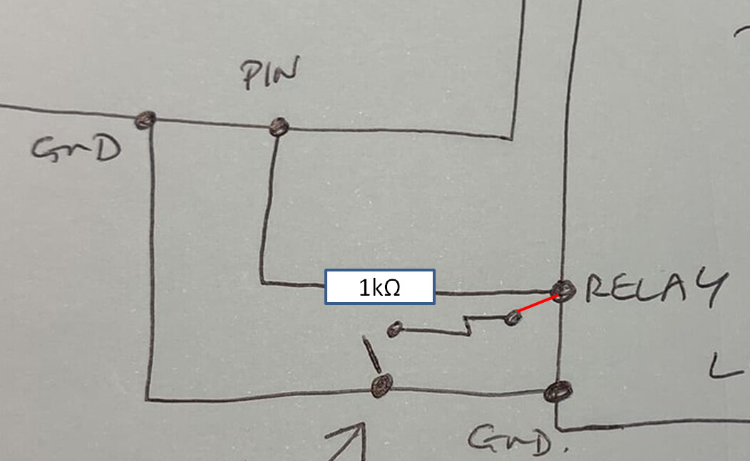
If the pin of the switch is intended to be connected as shown by my red wire, then it wouldn't be a good idea to short the high Arduino pin output to Gnd. Adding a 1k resistor would make it safe. The resistor would limit the current from the output pin to 5mA.
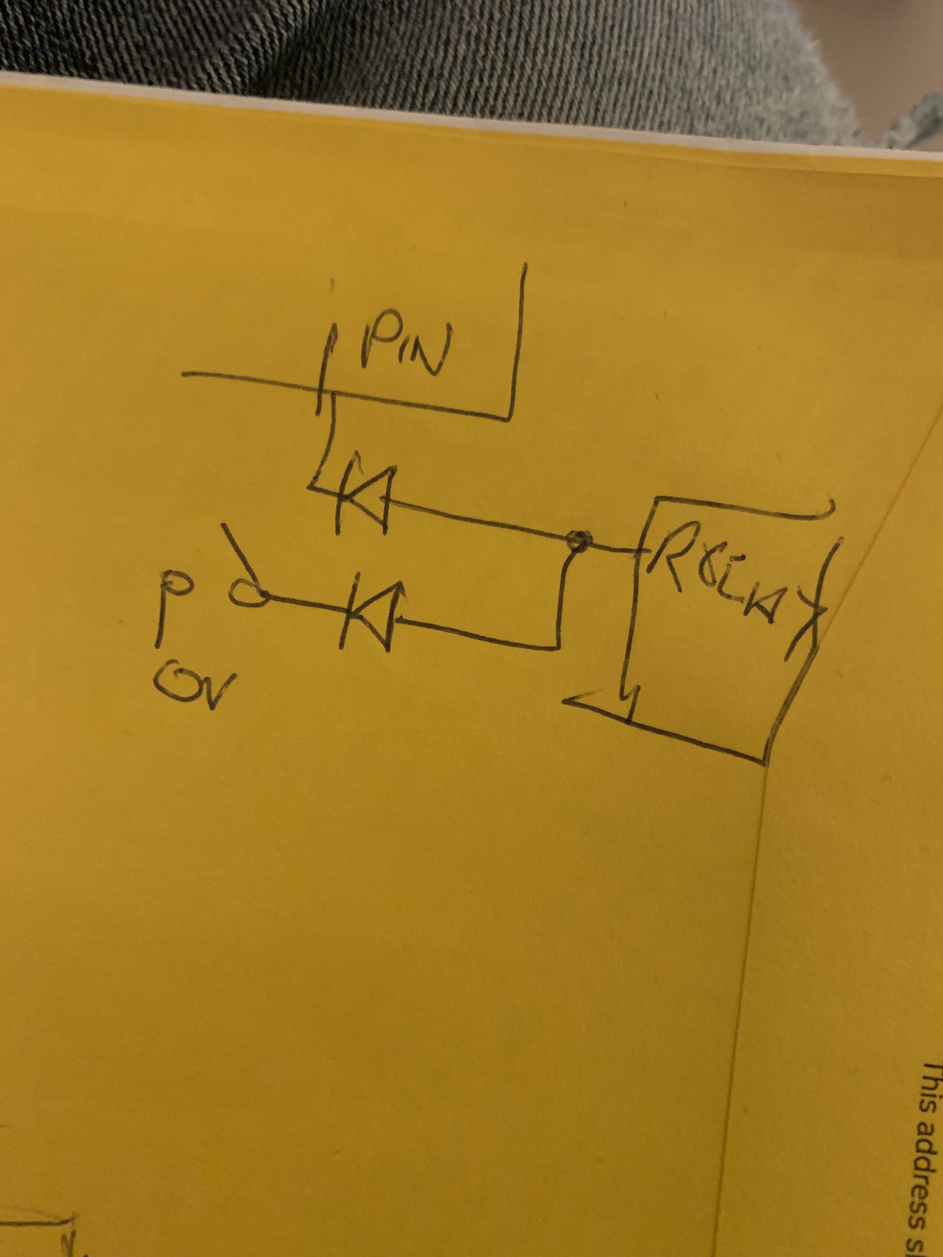
Put a pull-up resistor on the input to the relay board, then a diode to the Arduino output pin so that it can only pull the input to the relay board low. The switch is then connected from the relay board input to ground.
The pullup resistor may not be needed, the typical opto-isolated relay board uses the input to provide the ground path for an LED inside the opto isolator.
I'd use an SPDT switch. Common terminal to the relay board, one "throw" terminal to the arduino, the other terminal to ground. That way, regardless of arduino state, you can activate the relay without potentially causing damage.
@cedarlakeinstruments : The switches are small momentary ones to go onto a model railway control panel, so SPDT would be a) more exepnsive and b) take up too much land space
So if I use a diode, what diode would I use and which way would I orient it. (Sorry but not up to speed yet on electronics). Could it be combined with the resistor idea of @Dave_Lowther ?