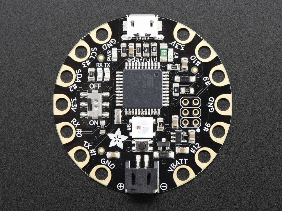
Hello, first time posting! I am trying to get data transmission between 3 microcontrollers (Adafruit Flora V3) such that two slave boards collect data from many sensors, then transmit this data to a third master controller for interpretation.
The issue I have is I don't know how to tell the software that I want the slave to "pay attention" to pin D10 for the interrupt trigger (as opposed to I-don't-know-what), so both slaves broadcast to the master simultaneously. I would love to be told that if I put "foo40k" into the ISR function below, then the program will tell the controller that the interrupt will come from pin D10.
My current slave code for this process is virtually unchanged from an example I found by Nick Gammon:
//-------------------------------------------------------------------------
void setup (void) {
pinMode(MISO, OUTPUT); // have to send on master in, slave out
SPCR |= bit(SPE); // turn on SPI in slave mode
SPCR |= bit(SPIE); // turn on interrupts
} // end of setup
volatile char buf [50] = "Goodbye, world!";
volatile int pos;
volatile bool active;
// SPI interrupt routine
ISR (SPI_STC_vect) {
byte c = SPDR;
if (c == 1) { // starting new sequence?
active = true;
pos = 0;
SPDR = buf [pos++]; // send first byte
return;
}
if (!active) {
SPDR = 0;
return;
}
SPDR = buf [pos];
if (buf [pos] == 0 || ++pos >= sizeof (buf)) {
active = false;
}
} // end of interrupt service routine (ISR) SPI_STC_vect
void loop (void) { } // end of loop
//-------------------------------------------------------------------------
I have a background in mathematics rather than coding, so I understand things like how the individual if statements work, but I don't know things like whether "SPDR = buf[pos++];" increments before or after transmission, or why the master uses SPI.transfer(char c) while the slave uses SPDR = char c. Insight to these are appreciated, but I only need to know what to write to have a functional interrupt set to D10 on a Flora. I will attach a chart of the Flora pinout that looks like it could be helpful to solving this problem. Thanks in advance!
unuoctium:
The issue I have is I don't know how to tell the software that I want the slave to "pay attention" to pin D10 for the interrupt trigger (as opposed to I-don't-know-what),
This is not a software issue. This is a hardware function, the software would not be fast enough. When SPI is used in slave mode a special pin usually called SS (slave select) or CS (chip select) are used to tell the slave that the master is accessing it.
In your case the SS pin seems to be the one connected to the RXLED PB0 Pin8 according to your pinout diagram. This matches the atmega32u4 datasheet. You might be able to configure an alternate pin as SS if it is supported by the SPI module. Please check the datasheet, I did not find one (but looked only for two minutes). In any case, it will not be any pin you like, because this would require a complex pin matrix, which cost silicon area.
http://ww1.microchip.com/downloads/en/devicedoc/atmel-7766-8-bit-avr-atmega16u4-32u4_datasheet.pdf
Based on this information, I was able to find better documentation regarding my board. I see that it uses the atmega32u4-au (image included), which is hopefully different from the non-au atmega. I see that "8" is still RXLED/SS, but I'm not sure which pin on the board I own is #8. In the (included) picture of a Flora board, it appears that #8 is one of the 4 wires leading into the RGB LED; this suggests to me that it's not practical to use #8 as the interrupt. Is this the impression you get as well?
If this is the case, I would like to declare a different pin as SS/CS. If I do find an alternative, what would I need to write into the code to use this other pin as the hardware interrupt? Would it be possible for me to use the alternate-interrupt code to test-and-check for a pin which works as intended? I also don't mind if the solution is comparatively slow to "true" SPI, I'm just trying to have something which works in the first place.
unuoctium:
In the (included) picture of a Flora board, it appears that #8 is one of the 4 wires leading into the RGB LED; this suggests to me that it's not practical to use #8 as the interrupt. Is this the impression you get as well?
No, the RGB LED is a NEO-Pixel and is connected to Pin28 on the schematic. It uses a serial protocol and therefore only one pin.
The SS pin is the small yellow color LED marked RX near #3 on the photo of the board. You should still be able to use the SS pin with the RX LED connected. You might need to solder a wire to the board.
As I said I could not find an alternate pin in the datasheet. Sometimes you can write into a register and route the function to another fixed pin, but I did not find one for this case.
Another alternative might be to use I2C. You will need to check the datasheet (link in last post chapter 20). It looks like it supports master and slave and you can have up to 127 slaves. Should be enough  You will need pin #2 and #3 on all boards.
I have taken your advice and switched to using I2C instead of SPI. The transition has been interesting, and overall a pretty huge improvement in quality of life.
At this point, the wiring I have on my devices (a "master" board, a "right", and a "left" board) is all SCL are on one line, and all SDA are on one line. I have been using I2C in the void setups to check for when all 3 devices are turned on, before each proceeds to the void loop.
Nominally, I am trying to get the right board (I2C address 1) to receive "1" from the master, then to transmit "1" in response, and to repeat this with the left board (I2C address 2). However, the master tells me that it is receiving "3" from the right and "5" from the left, despite both boards executing Wire.write(1);. Do you have any suggestions offhand for how I can troubleshoot this issue? I have not been able to find anything to help me in this regard. I have attached each of the sections of code I have written thus far, in case that could be helpful, though I suspect my issue is a common one I'm simply unfamiliar with.
ME_Master.ino (7.73 KB)
ME_Right.ino (13.1 KB)
ME_Left.ino (13.1 KB)
I would create a very simple sketch and just send bytes back and forth until that works. Make sure your I2C has pull-up resistors.
I noticed you use a lot of comments in your code. If you change the code a little bit by choosing better variable names you could remove quite a lot of the comments. Comments can get out of sync with the code and should only be used for things the code cannot explain.
e.g.
Wire.beginTransmission(addressL); // open transmission with the left sensor
Wire.beginTransmission( leftSensorAddress );
or
if(interruptType == 1) { // ---VOID SETUP HANDSHAKE---
enum { REQUEST_TYPE_HANDSHAKE, REQUEST_TYPE_LINES, REQUEST_TYPE_DATA }
...
if( requestType == REQUEST_TYPE_HANDSHAKE ) {
The formatting makes the code quite hard to read. You can use the Arduino IDE Tools -> Auto Format function to create nice clean code formatting. It can be configured to your taste using a formatter.conf file.
# This configuration file contains a selection of the available options provided by the formatting tool "Artistic Style"
# http://astyle.sourceforge.net/astyle.html
#
# If you wish to change them, don't edit this file.
# Instead, copy it in the same folder of file "preferences.txt" and modify the copy. This way, you won't lose your custom formatter settings when upgrading the IDE
# If you don't know where file preferences.txt is stored, open the IDE, File -> Preferences and you'll find a link

mode=c

# 2 spaces indentation
indent=spaces=2

# also indent macros
indent-preprocessor

# indent classes, switches (and cases), comments starting at column 1
indent-classes
indent-switches
indent-cases
indent-col1-comments

# put a space around operators
 pad-oper

# Insert space padding around paren on the inside only.
 --pad-paren-in -D

# put a space after if/for/while
 pad-header

# Move opening brackets onto new line
 --style=allman --style=bsd --style=break -A1

# Insert space padding around operators.
 --pad-oper

# if you like one-liners, keep them
 keep-one-line-statements
If you like to avoid global variables but need it next time the function runs, you can use static variables instead. e.g.
void loop()
{
  static int loopCount = 0;

  loopCount++;

...

}
I have gone through the code and done an overhaul of variable names, comments, and some minor modifications to the actual program. I have also removed most of the redundant comments, though there is likely still an above-average number of them, as the goal is to make the thought process clear to other beginner-level programmers. I'll start looking more into the auto-formatting of Arduino, as having that be automated would be very nice.
The issue I faced previously had to do with the void setup, so I created a snippet of each function and retained only the relevant variables + code to turn the NeoPixel off (it turns on to a semi-random color on boot otherwise). Even in this state, I still have the same issue of the sensors/slaves receiving values from the master correctly, but the master receiving the same incorrect values. I have tested wiring one 5k-ohm resistor from each 3.3v output of the Master Flora to each of the SCL and SDA circuits; this does not change the values sent/received. Preliminary research indicates that the Flora could be using internal pull-up resistors already, though I doubt this is happening.
I have looked some more for others who have had this problem, though to no avail. I have included the .ino files for the complete program and files for the snippets, though my best suspicion is now that the problem lies within a while loop in the master code. If the issue is in one of the left/right code, the only meaningful difference is a change in slave address.
bool AllSystemsGo = false;
while(AllSystemsGo == false) {
// First, check the right sensor
Wire.beginTransmission(rightSensorAddress);
Wire.write(1);
Wire.endTransmission();
Wire.requestFrom(rightSensorAddress, 1);
byte RightReady = Wire.read();
// Next, check the left sensor
Wire.beginTransmission(leftSensorAddress);
Wire.write(1);
Wire.endTransmission();
Wire.requestFrom(leftSensorAddress, 1);
byte LeftReady = Wire.read();
if(LeftReady == 1 && RightReady == 1){ AllSystemsGo = true; }
}
Thank you for all your help, I sincerely appreciate it.
Snippet_Master.ino (4.8 KB)
Snippet_Left.ino (4.3 KB)
Snippet_Right.ino (4.3 KB)
ME_Master.ino (10.2 KB)
ME_Left.ino (16.6 KB)
ME_Right.ino (16.6 KB)