You have questions? Just ask. Things like these little igniters have fascinated me for years. ![]()
Ron
Keep something in mind. Measuring across the roughly 1.0 Ohm motor igniter is once that igniter fires the igniter circuit is now open loop with 12 volts across where the igniter formerly was. ![]() Consider that as to your uC.
Consider that as to your uC.
Ron
I will run a simulation Once I finish drawing the circuit. But the R7 should bring the current down to 5v or lower. Otherwise, I can add a component to switch over when we arm the Ignitor.
It's not about the current or current limiting. When R1 (the ignitor) opens the input impedance to your analog is about 10 Meg Ohm. R7 the 47K isn't going to do anything. Yes, I suggest you run the sim on that. When the anode of D1 goes above 5.7 volts D1 will be forward biased. Actually as drawn in post #12 unless M1 MOSFET is On I don't see any path to ground? Unless the Pyro_Test through through R6 is a push to test button to groundand even then R1 the igniter has no path to ground? I am missing something somewhere. ![]()
Ron
D1 , limits volts in to vcc+0.6v
OK assuming a common ground on the 5V and 12V supplies I am seeing right about 5.6 volts to the analog input. Depends on the diode. So not shown is the common grounds, would that be correct?
Ron
yes , limited in current by a 47k resistor . well within the safe operating limits
common ground is essential
Otay, now the picture makes more sense. Thanks kindly for the explanation. ![]()
Ron
Hi, I finally finish the Pyro Diagram. I used a MUX to use fewer pins. I have a few questions, just to make sure I am Drawing Correctly.

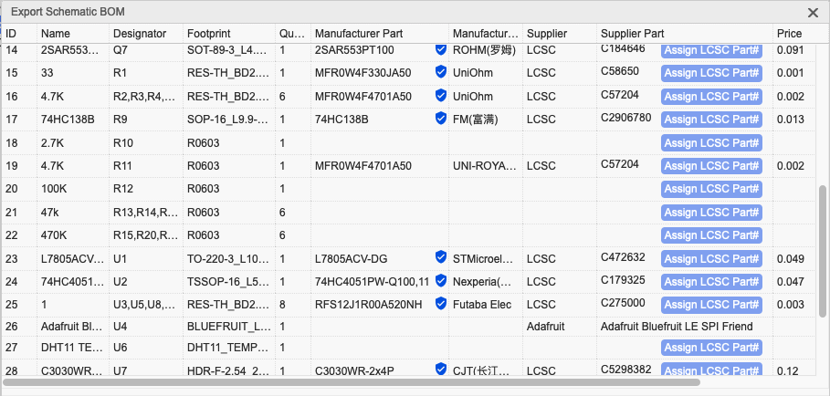
In the Pyro Diagram, there is a 470k resister Like R15 and a 100K resister like R12.
The 470k, Is this a typo Should a 47K resister do the Job to protect my Teensy pin?
For r12 is 100k ok, or too Much?
I have included the BOM file Image for reference
Thanks
We finally finish the Flight Computer. Took me a long time and a hospital stay. But it's done. Will begin testing once I get it all assembled. The rocket's Small Silver(60cm) is Printed and almost ready to go. Big Silver(130 CM) is still in Production. Should be done Middle of next week. The flight computer is for Big Silver to control TVC engin and the Return to Home with Wing Parashut.
I will be back on the operating table tomorrow and out by Wednesday. After a few days of rest and I will start the assembly and testing of the computer. If all goes well 1st flight test will be in May.
Here are some features of the Flight Computer.
Full-featured dual deploy/multi-stage/air start rocket flight computer capable of 100,000ft or more
Tilt-sensing lockout for ignition of second stages and/or air starts
Live telemetry over fil NRF24L01+PA+LNA compatibles with Arduino – 2 Mbit/s – 1100 metres And Bluetooth BLE
6 high-current pyro outputs with continuity checks
Advanced MEMS sensor package: GNSS, accelerometers, gyroscope, magnetometer, barometer, and LoRa radio
High Data-Capture rate: approximately 50,000 samples per second recorded to SD card
–1000Hz 3-axis digital 24G and 100G accelerometer data logging
–1000Hz 3-axis digital 2000dps gyroscope data logging
–1000Hz of flight events & continuity data logging
–1000Hz of sensor-fuzed speed & altitude
–100Hz of pitch, yaw, roll rotation
–40Hz of magnetic data logging and magnetic roll
–30Hz-100Hz of digital barometric data logging (Altitude, pressure, temperature)
–30Hz of main battery voltage (1400Hz during pyro events)
–5Hz-25Hz of GNSS data logging (chip-dependent data rates & constellations)
–Separate data file for each flight up to 100 flights
Simple, easy-to-use configuration interface through the SD card
–User Selectable Flight Mode: Single-Stage, Two-Stage, Air start, or Booster
–Configurable Apogee delay
–Optional Audible Battery Voltage report at startup
–Optional Magnetic Switch Startup & Shut-down
–Pre-flight audible reporting options: Perfect flight or Marsa
–User-selectable telemetry frequency & power settings
–8 configurable servo outputs (8 powered) +4 Multy prepose
–User-selectable inflight brownout recovery
Mach immune, sensor-fusion-based apogee event
Barometric-based main deploy event
Audible pre-flight continuity report
Audible Post-flight max altitude & speed report
Mount in any orientation, automatic orientation detection with built-in self-calibration mode
Bench-test mode activated w/ tactile button, user configurable status messages over USB Serial
A report in SI or Metric units
GPS Ubox
I wanted to see how much I could pack into this board. This board can be used for a drone or a Rocket.
![]()
Good flight
Hard to believe this started with an ignitor. ![]()
Ron
1 Like
Because of the rocket ![]() ?!
?!
This topic was automatically closed 180 days after the last reply. New replies are no longer allowed.
Hello, Well Here is the Final design I have for the Pyro continuity test and the Ignition of the Pyro. This is a followup on : [How to test for Pyro Channel (Continuity) Short](https://forum.arduino.cc/t/how-to-test-for-pyro-channel-continuity-short-the-ignitor-is-not-connected-or-the-ignitor-is-bad/1092661)

Been a Bizzy Year so the Project is Going Slow. But I am almost finished.
What do you think of this Schematic? Did I render it Properly?
@stevemj Does this respect your Schematic?
Thanks
Pierre
The original topic has been reopened and the new topic following on from it has been moved into it
That looks fine to me :slight_smile ![]()
One very minor thing didoe D7 could be a smal signal dioded 1n4148 for example. But not big deal.
Best of luck.
Thanks! I putting the final touch on the Computer board and I will publish it once I have tested it.