

and when i upload it its said uplod is done but when i press button on my ir remote nothing is showing on serial monitor and my serial monitor also look different .pleas guide me what I'm doing wrong

- Let’s see a good image of the wires going to the receiver and their connection to the power pins.
This should show the silkscreen on the receiver PCB.

- This should show the silkscreen on the receiver PCB.
What should i do can i explain it please
Tilt the breadboard at a 45° so we can see the markings on the receiver.
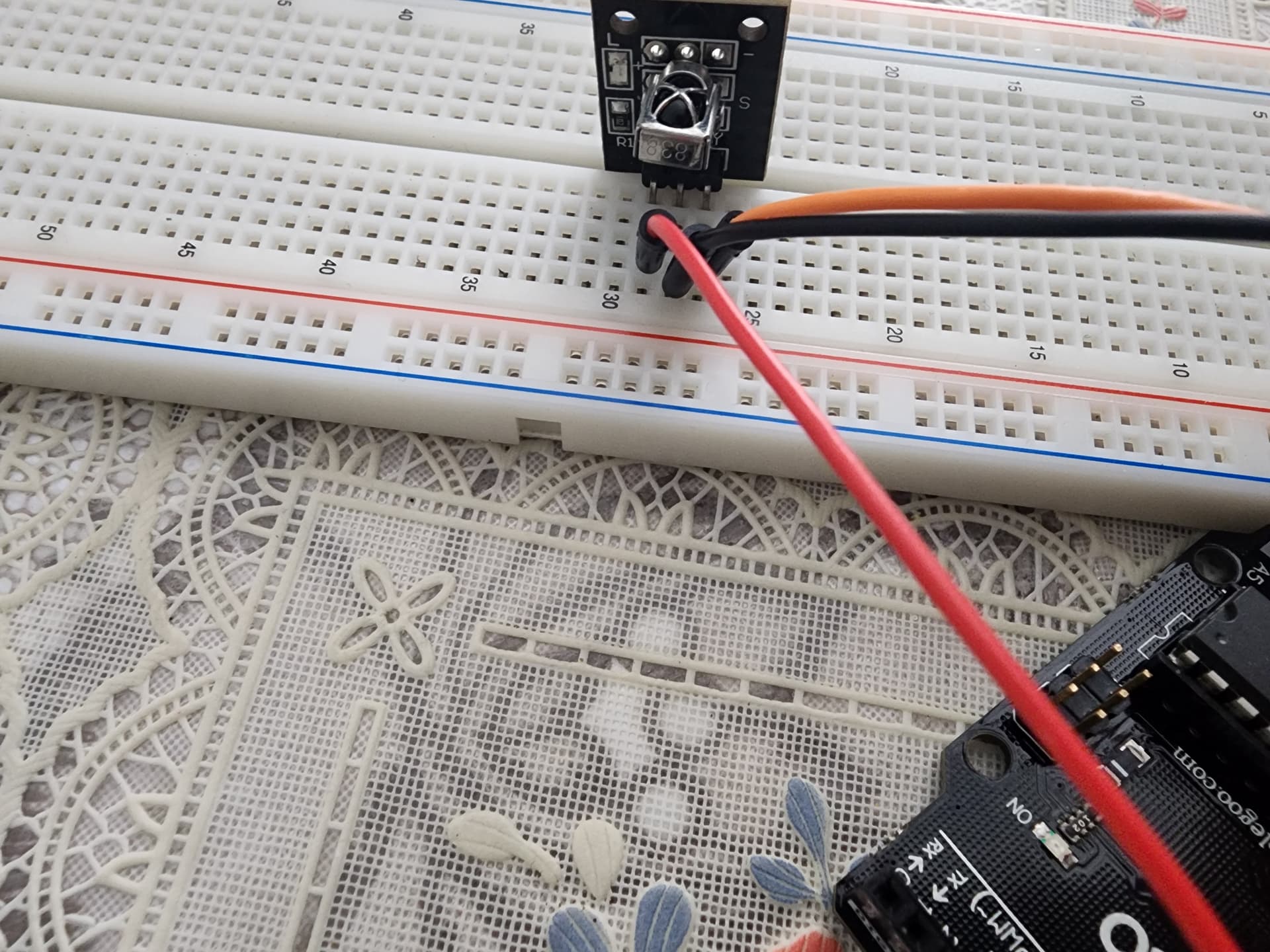

Sorry but we need to see the whole front of the board so we can check any white lettering near the connector.
One more picture please.


Yes i connect like this still serial monitor is not working and my remote
I fix it how you told me in the picture still same thing
- Copy your code/sketch and paste it here for us to look at it.
No pictures please.
#include <IRremote.hpp>
IRrecv IR(11);
void setup() {
// put your setup code here, to run once:
IR.enableIRIn();
Serial.begin(9600);
}
void loop() {
// put your main code here, to run repeatedly:
if (IR .decode()){
Serial.println(IR .decodedIRData.decodedRawData,HEX);
delay(1500);
IR.resume();
}
}
-
First off, you do not need this line of code delay(1500);.
-
Your code works fine here.
-
If your wires are all good, you must have damaged your receiver when you wired it wrong.

1 Like
Thank you i will order new ir receiver and try again
Not all IR receivers are wired the same. Dronebotworkshop covers this here (at 19:18).

Also... in the wayback time machine, the SQUARE solder pad on all connectors was PIN 1 GND (so, for this, Pin 1 is GND). Also, note the "-" minus silk screen... probably meaning GND.

You can see how the traces cross on the back of the board from IR receiver to pin.