I'm searching for Latching Relay to save energy. In a normal relay, there is IN1 pin which is the relay pin that receives signal or command from the RFID through Arduino. But It is different on Latching Relay which is only T pin not IN1. I only know T is a low pulse trigger. But what does it mean? Is it just the same? Can we just use it like an IN1 pin?
and if not, how do I use the latching relay controlled by the RFID reader through the Arduino?
As far as I know there's no standard of how these pins are named. Anyway, usually the coil to control the relay uses two pins, one of them might be constantly connected to the power source.
A latching relay should have 4 such pins, one pair for each latching position. You give a short pulse (a few centiseconds should be enough) to such a pair to change the relay output to the corresponding position.
Either is easily controlled by the Arduino output pins, though probably not directly.
The last dual coil relay I read about needed 4.5 ms to switch and 10 times that to fully guarantee a latching action. 50 ms would be OK, read the data sheet for an exact figure.
Pulses easily synthesized by program logic. Do not leave any coils energized beyond what is needed to accomplish the switching/latching.
What exact relay or relay module are you talking about?
Your reference to things such as "IN1" indicates that you are referring not to the relay itself, but a relay module with the relay and support components necessary to connect to an Arduino.
Unless you cite (Web links) actual relays or modules, discussion is simply nonsense.
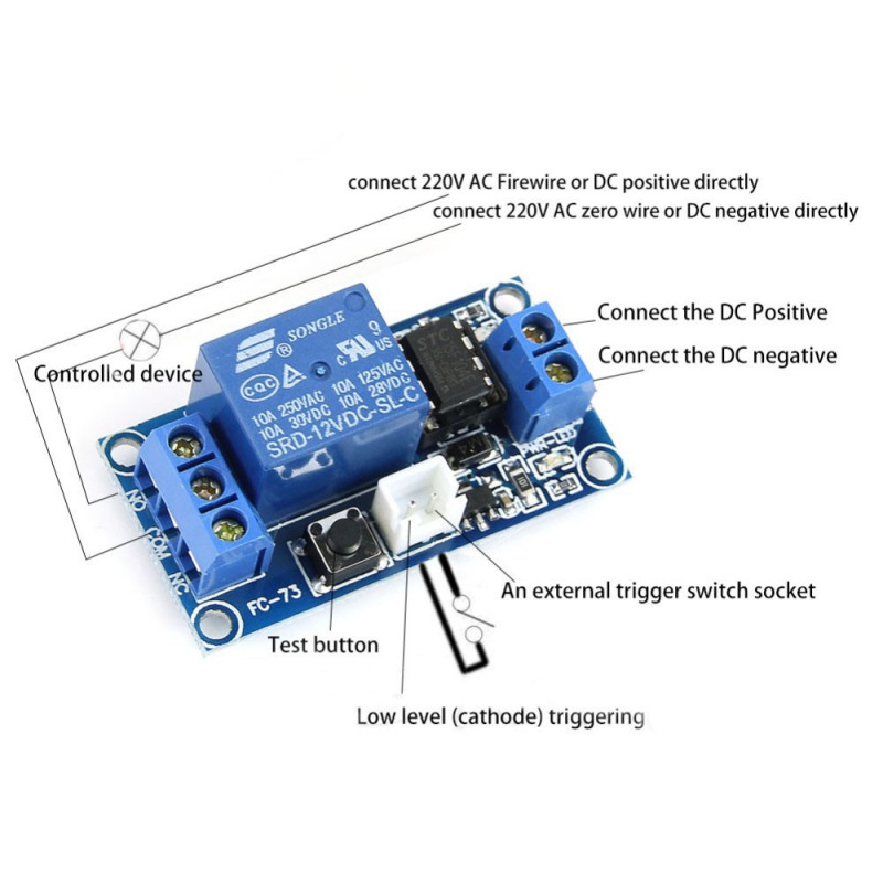
What you're describing is a latching relay module that would use a SONGLE (or similar) relay that needs continuous power on the coil to remain energized. Yeah, they latch, but definitely no energy savings.
You need a true latching relay where its single or dual coil is impulse driven. High energy savings here plus "memory" in case of power loss where the relay contacts will remain in their last driven state.