Can't seem to get the UC3708 wired up correctly with the Arduino. I'm trying to use 12vdc as the source to be switched. It seems to add or subtract a few volts from 12 when it is operating depending on the wire locations, but no 0v or 12v when operating like I think it should. Thank you.
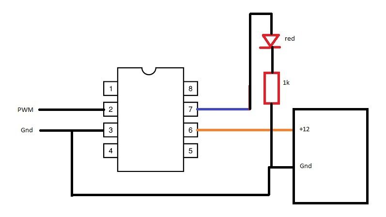
It might help if you show us your schematic diagram. At the moment we can only guess as to what the problem is.
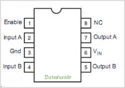
Output A = 12v Drain
Vin = 12v Source
Gnd = Arduino ground
Input A = PIN 12
Do I need to put something on the enable pinout?
N2GN2:
Output A = 12v Drain
Vin = 12v Source
Gnd = Arduino ground
Input A = PIN 12
That's not a schematic. Draw a full schematic of your connections, both to the Arduino and to the power MOSFETs that the chip is driving. (Are you driving MOSFETs, or something else, for that matter.)
Do I need to put something on the enable pinout?
Are you saying that you just left the enable pin floating? Did you try connecting it to +5V?
Yes I've tried enable pin 5 volts and floating. Do you know about the other pins on the chip?
@Runaway Pancake, that seems to do the trick. Normal state shows 0.18vdc on the output pin, 11.5vdc when activated. Do you know why the Arduino pin 13 LED light stays illuminated now? I moved PWM to pin 11. Thank you.
N2GN2:
Do you know why the Arduino pin 13 LED light stays illuminated now? I moved PWM to pin 11. Thank you.
Post your sketch.
It should only go on with a digitalWrite (or some inadvertent external connection to it.)