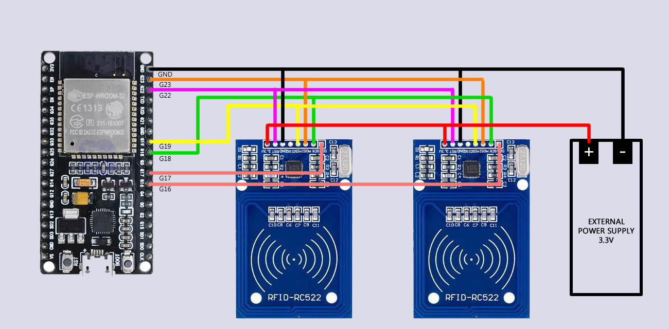
The result is very inconsistent. Sometimes 1 out of the 3 readers is working, most of the time none of them.
I've tried with 2 readers as well, it works sometimes, but still very inconsistent.
I took inspiration from this project where it seems to work fine with 4 readers.
Would any of you has some clue about why it's not working for me or how I could debug this?
Here are the wiring and code details of my implementation:
The wiring looks clean but the MFRC522 is very picky with SPI timing and wiring length
If you get inconsistent reads with multiple modules it’s usually one of these:
shared SPI lines too long → signal integrity problems
3.3V supply not stable enough (these readers draw more than people expect)
no separate pull-ups / noisy MISO line when multiple readers are idle
all readers waking the SPI bus at the same time
If I were debugging this, I’d start simple:
→ test one reader with very short wires
→ then add the second
→ then the third
If it breaks as soon as you add the next one it's almost always a hardware / noise issue, not the code
  const byte RESET_PIN = 22;
  .
  .
  .
  for (uint8_t i = 0; i < NUMBER_OF_READERS; i++) {
    mfrc522[i].PCD_Init(CS_PINS[i], RESET_PIN);
By using the same reset pin for multiple readers, you first reset all readers, initialize the first reader, then reset all readers again, including the first reader, initialize the second reader, and then reset all readers again, including the first and second readers before initializing the last reader.
@van_der_decken This makes absolute sense, thank you!
I've tried with a dedicated pin for each reader's RST and it's much better now.
I still have inconsistency with 1 reader though, but after a few tests, I believe the reader is faulty.
I've ordered a replacement unit and I will test again when I receive it, this is promising though. I'll make sure to update the thread when I have news
Also if the readers are too close together they will interfere with each other. This will reduce the range of the readers and sometimes stop them working.
Note when constructing them in a case, never use any metal fastenings. Always use nylon nuts and bolts.
I have made many projects that use three RFID readers in the past that use readers like this to generate the things you get in mixed up books.
Good to hear the separate reset lines improved things. That’s usually the first hidden issue with multiple MFRC522s on the same SPI bus. Even with good resets, keep an eye on the SPI lines: the MFRC522 tends to leave MISO floating when idle, so a single bad module can corrupt the whole bus. If the replacement fixes the inconsistency, then it was most likely that one faulty reader pulling MISO low or adding noise
@Grumpy_Mike I'm not sure to understand, my ESP32 is a 3.3V, not a 5V, do I still need these resistors ?
I'm building an educational toy for my kid. The goal would be to place cube letters on a board, these letters get recognized and the toy will read it on a speaker.
@maikarg Probably, but my final application would be on a smaller board with a single bus, so I'd like my prototype to work with a single bus.
No, if the whole system is 3V3 you do not need the resistors.
Thanks, but I am not too sure what you mean by cube letters.
I have found that it is best to scan the readers one at a time while disabling the others. This way there is less interference. If you look at the video I posted you will see it is from a MagPi magazine article I wrote. You can get a free PDF download of the whole magazine and check out what hardware I used.
Sure the software is written in Python, but could equally well be written in C/C++ on an Arduino.
No, you understood the question. But you would be amazed/appalled at how many people think they're going to get reliable electrical connections across multiple pins by simply sticking header pins through the holes... so I'm glad it was a silly question!
Can't say as I've ever fried one of those modules. And you're running everything at 3.3V so there's not even any potential 5V issues.
The only thing I've got, and it's a long shot (and something I've never seen with these) is one of the modules not tristating MISO when it's not selected. That could damage one or more modules if a non selected module left MISO as an active high when the selected module was driving the line active low. Like I say, I've never seen it myself so I've got no idea if it's a real potential problem or not, but I have seen it mentioned.
Unless... have you measured the output from your external power supply to see that it really is 3.3V?
Oh, interesting. Then, this whole solution of sharing the MISO between modules and switching the selected module could damage it. @Grumpy_Mike have you ever experienced that with your "Mixed up robots" project ?
After sleeping on it, even if "MISO not being tristated when the board is not selected" is a real problem with MFRC522 boards, I don't see how it could be what's causing your boards to die after some time. They simply wouldn't work from the start when you had two or more boards connected.
No but that is because I used a different circuit, designed specifically for the Raspberry Pi, and was all soldered up, no solder-less bread boards. I have been doing a bit of work with solder less bread boards, with the Pi Hut's Advent calendar, (my son bought it for me) and they are very un-reliable at making contact. My guess is that the intermittent connection they provide could be the cause if you frying something
Anyway I think what we are missing from you is a picture of all your boards when connected together, not just the individual module.
By the way, sometimes I disconnect the power supply before disconnecting the ESP32.
So the modules are powered through the SPI lines for a second before I disconnect the ESP32 (I can see the module's LED flickering).
Is it possible that this could fry the module ?