firashelou:
i got a little bit confused here
what do u mean here 10 vs 1, 9 vs 2
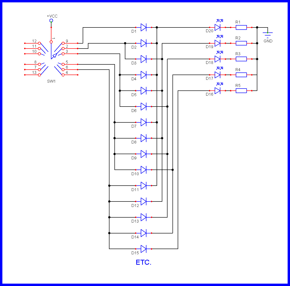
You have a varying voltage divider based on where the switch is set. In a way, this setup is like a potentiometer but it is digital with 12 positions, not analog. If all the resistors are the same value, then the ratio of the resistors to the "left" (connected to 0V) and to the "right" (connected to 5V) of the "wiper" (formally, the switch pole) is going to be able to be represented by two numbers, the number of resistors to the left of the "wiper", let's call that A, and the number of resistors to the right of the wiper, let's call that B, and they must add up to 11 for the simple reason that there are 11 resistors. The voltage at any point for the "wiper" is going to be A/(B+A), the number of resistors to the left of the wiper "vs" the number of resistors to the right of the wiper because of the fact that resistances in series sum and the voltage divider law.
At position 1, there are no resistors to the left, A is 0. B must be 11. Voltage = 0/(11+0) = 0 * 5V = 0V
At position 2, there is 1 resistors to the left, A is 1. B must be 10. Voltage = 1/(10+1) = 0.91 * 5V = .454V
At position 3, there are 2 resistors to the left, A is 2. B must be 9. Voltage = 2/(9+2) = 0.182 * 5V = .909V
etc...
At position 11, there are 10 resistors to the left, A is 10. B must be 1. Voltage = 10/(1+10) = 0.909 * 5V = 4.54V
At position 12, there are 11 resistors to the left, A is 11. B must be 0. Voltage = 11/(0+11) = 1 * 5V = 5V
firashelou:
but why do you use these numbers from 1 to 11 :o , i mean why not just work with the voltage and resistor ?
Good question. I was wondering that!
Take for example switch position 3. The voltage should be +0.909V and the digital reading should be 186. However due to noise and/or resistor value tolerances you will need to accept readings that are not exactly 186.
You could do something like this:
if(reading>169 && reading<206)
{
// code for switch position 3
}
Alternatively, with reference to my previous post:
position = 1 + (reading+47)/93;  //integer division

if(position==3)
{
// code for switch position 3
}
I totally agree. I wasn't trying to imply you should use those exact values. Those are the values under perfect circumstances. Most people only buy 5% resistors anyway. Use a range of values in your code, check it with the multimeter, make changes if there is a value or values that are outliers. But overall the concepts used here are very simple.
Take for example switch position 3. The voltage should be +0.909V and the digital reading should be 186. However due to noise and/or resistor value tolerances you will need to accept readings that are not exactly 186.
You could do something like this:
if(reading>169 && reading<206)
{
// code for switch position 3
}
Alternatively, with reference to my previous post:
position = 1 + (reading+47)/93; //integer division
if(position==3)
{
// code for switch position 3
}
ah ok ! so a method to give the exact number 3 or the number needed
firashelou:
hello Guys,
i would like to know if a 1/4 W resistor can be used here to connect between the pins of the switch or 1/2 W it should be ?
If you are using 1K resistors then the resistor network is 11K ohms in total. So you will never have more than a few hundred microamps going through it. You can use 1/8W or even less. I don't think anyone manufactures a resistor with a power rating so low that it would ever cause a problem.
JoeN:
If you are using 1K resistors then the resistor network is 11K ohms in total. So you will never have more than a few hundred microamps going through it. You can use 1/8W or even less. I don't think anyone manufactures a resistor with a power rating so low that it would ever cause a problem.
aha great amazing so the resistors won't make any problem in dimensions space
well i just finished trying it with the 4051 IC Analog multiplexer so i had some problem which is the pin number 3 of the rotary is giving a value of 0 and pin 1 is 202, pin 2 is 100 something, the pin 5 is 1023 and it gets down to 200 something as i recall for the pin 11
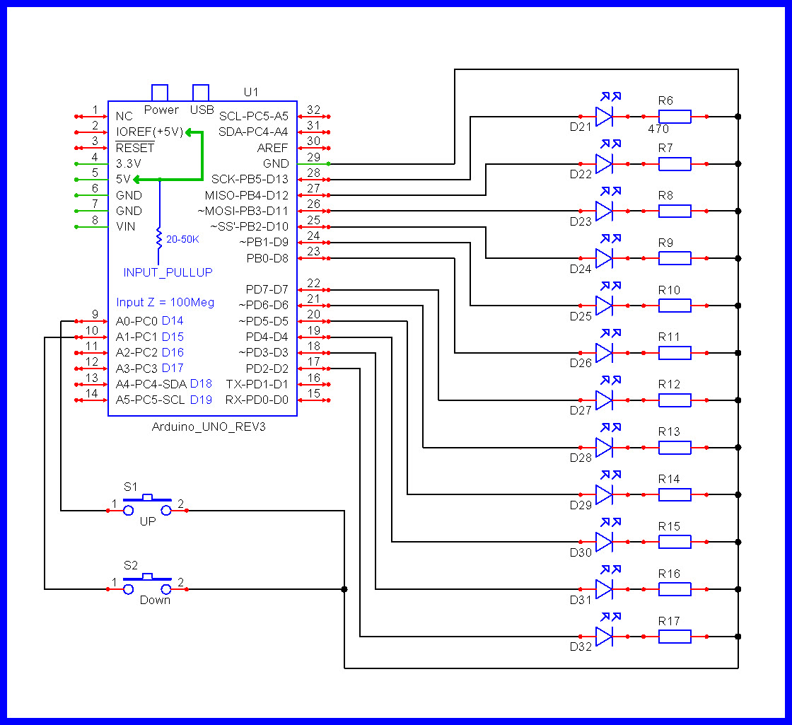
Has anyone wired this 12 pos switch so that some leds can ( as in a 9 LED Minorah candle ) can be lit...one at a time, additionally. Such that some action ( rotary, or other) selects one led, then one and two, then one and 2 and 3, etc.?
I'm a led lighting artist, but not an electronics genius.
Ray Locke, Venice, fl