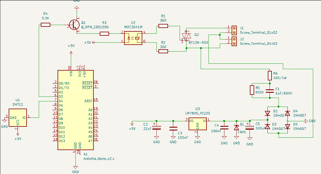
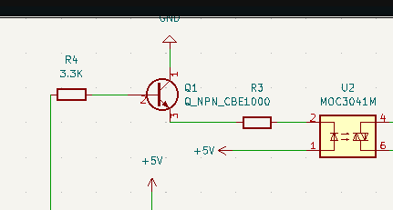
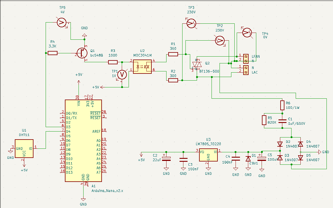
Hello i just made a humidity controlled fan circuit and i got some problems with it. After i solder everything up correctly and power my circuit i get no results , what i mean by that my Control circuit works fine but my fan isn't spining at all. The circuit should recive the humidity lvl thrue sensor and depending on code i implemented it spits fill controlled PWM signal and by that Control the optotriack that than controlls triack which should regulate the speed of the fan but unfortunnly not od that happens and the triack stays open all the time and fan doesnt recive any power .Could u take a look and help me figure out what is going wrong ?
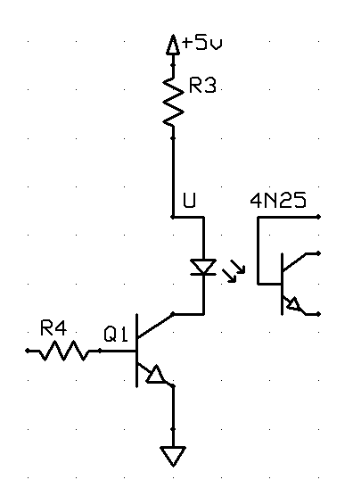
If your circuit is indeed wired as shown in the schematic (kudos for posting one, BTW!) it cannot work for the reason @herbschwarz states. I'd also put R3 in the collector circuit of Q1 for a more conventional look. Something like:
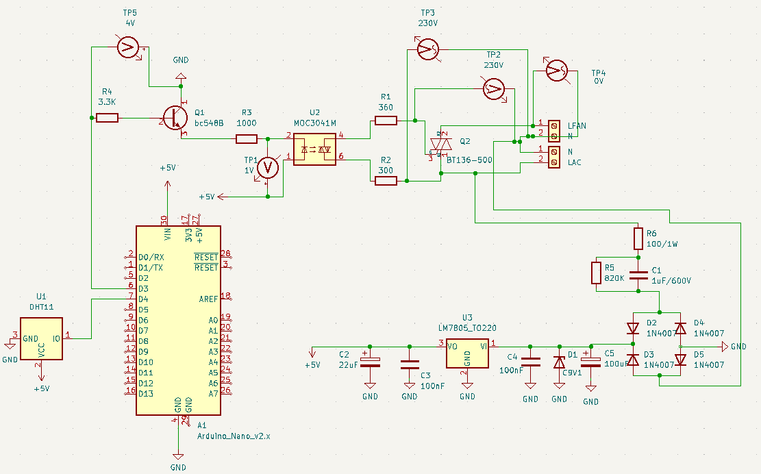
Hello , I made things that u sayed but the circuit still isn't working I mesured everything and i don't see anything that can cause that i also swtched a opto and triak for new ones just in case they were damaged but that didn't make any changes do you have any other ideas what should i measure or switch bcs im clueless. ( I added too the circuit some mesure points which are ofc ideological)
A note on schematic layout, if you're willing to listen. Always draw circuits with the more positive voltage above the more negative. In this case, the opto circuit would start with +5 at the top, then your isolator pin 1, the resistor, the collector of the transmitter, then finally at the bottom the emitter of the transmitter connected to ground.
Circuit layout in schematic form is a method of communication; part of the language of that communication consists of a number of layout standard practices; this is just one of them.
Thanks for reading this far.
Ok , i will try to implement what u just told me too my future projects . But i guess its more of art but in practical case my option should work do u see something in it that could cause my problems ?
Looks like rectifying 220V to feed to a7805? Better be in a bunker when you energize that, the 7805 will disappear. I'll say no more, you've no business messing with stuff like this if that's your level of electrical design knowledge. My only advice is for you to get some qualified help.
I guess u didn't notice its no transformer power supply consisting more than just 7805 , low voltage section is working just fine, Arduino is powered correctly and im getting proper low volage stearing soo its not the case . Also i have knowlage and and want to train it that's why i made that circuit and now i want to know what iam missing here to don't do same mistake again.
For future interested people the problem was with polarity of triack i didn't know that it is a difrence
in main terminal 1 and main terminal 2 and that caused my problem . I reversed it and everything is working like it should . ( Even 7805 didn't blow like last guy sayed and it don't even need any sort of radiator)