Hi,
To control my railway I use a module from Tams-Elektrinik, called WRM-4 - 4 fold turnout detector.

The connections are shown in the next picture:
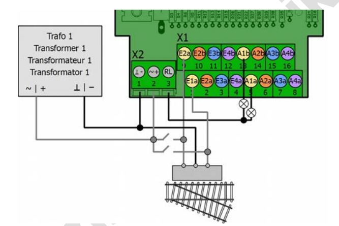
I don't wont to connect a led on A1a , A1b, A2a, A2b, A3a, ... and so on, but I want to get the signal into my Arduino to control and track the trains.
As the WRM-4 module has an output of +/- 20v (measured) I can't connected it directly to the Arduino. So I try to use an optocoupler.
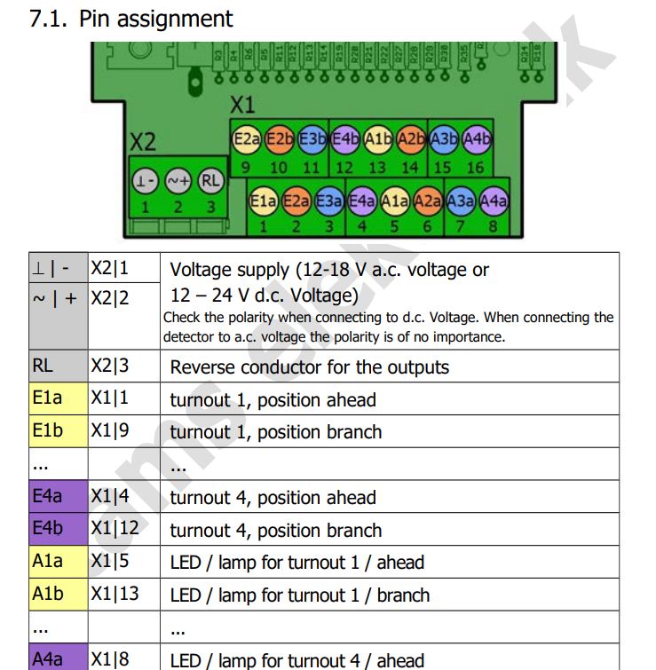
Here pin assignment of the WRM-4 module.
The optocoupler is the module HY-M154 or 817 module, also known as PC817 as shown here.

Inputs of 817 module
- IN1
- G1 (further mention as IG1)
- IN2
- G2 (IG2)
- IN3
- G3 (IG3)
- IN4
- G4 (IG4)
Outputs of 817 module
- V1
- G1 (further mentioned as OG1)
- V2
- G2 (OG2)
- V3
- G3 (OG3)
- V4
- G4 (OG4)
The WRM-4 module delivers on RL (X2/3) a "reverse conductor for the outputs). I don't understand this 200%, But when I measure the current between RL and 1 of the A1a, A1b etc, I got the +/-20V.
Important the RL = the "+" and the AXy is the "-".
So I have to connect the WRM-4 - RL to the 817 module IN1, IN2, IN3 and IN4.
the WRM-4 A1a goes to IG1 and so on.
Here the complete list of connections

The problem is no that the Optocouplers on the 817 module goes to high/active/ closed (I don't know how to call it) the led is on, When the WRM-4 RL (+ Voltage) is connected to the IN1.
Even when the A1a is not on.
Resulting that all the 4 ports are on.
I would expect to connect the WRM-4 RL to the Gnd of each input in the 817 module and the A1a, A2a, A3a, A4a, each to 1 input of the 817 module. But that's not working. (probably --> Reverse conductor for the outputs)
Who can Help ?
Thanks