MorganS:
No, you need to answer those questions. What frequencies do you expect to be measuring with this equipment? Do you expect to see digital pulses with reasonably square edges? If so, you need to take a lot more care with the layout.
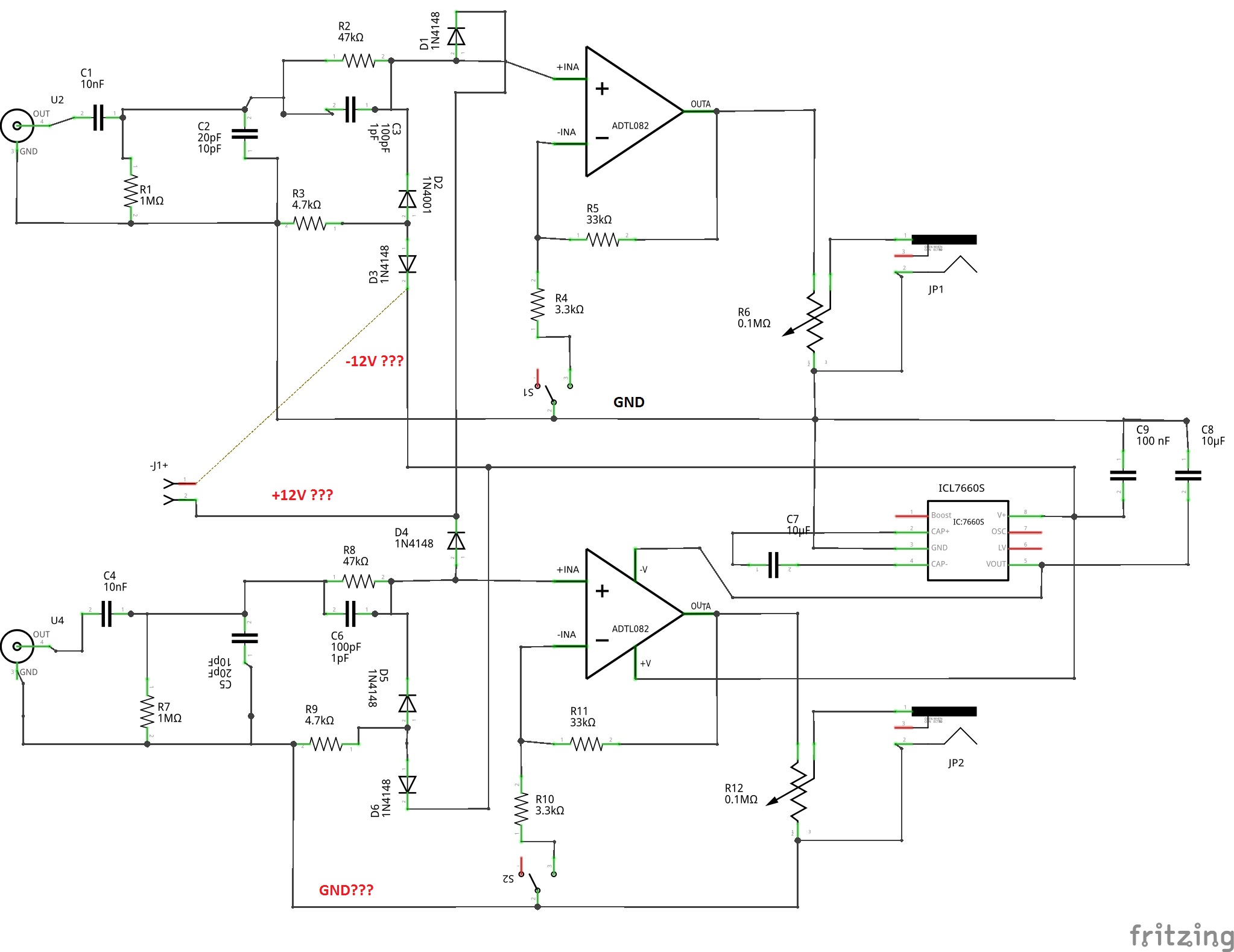
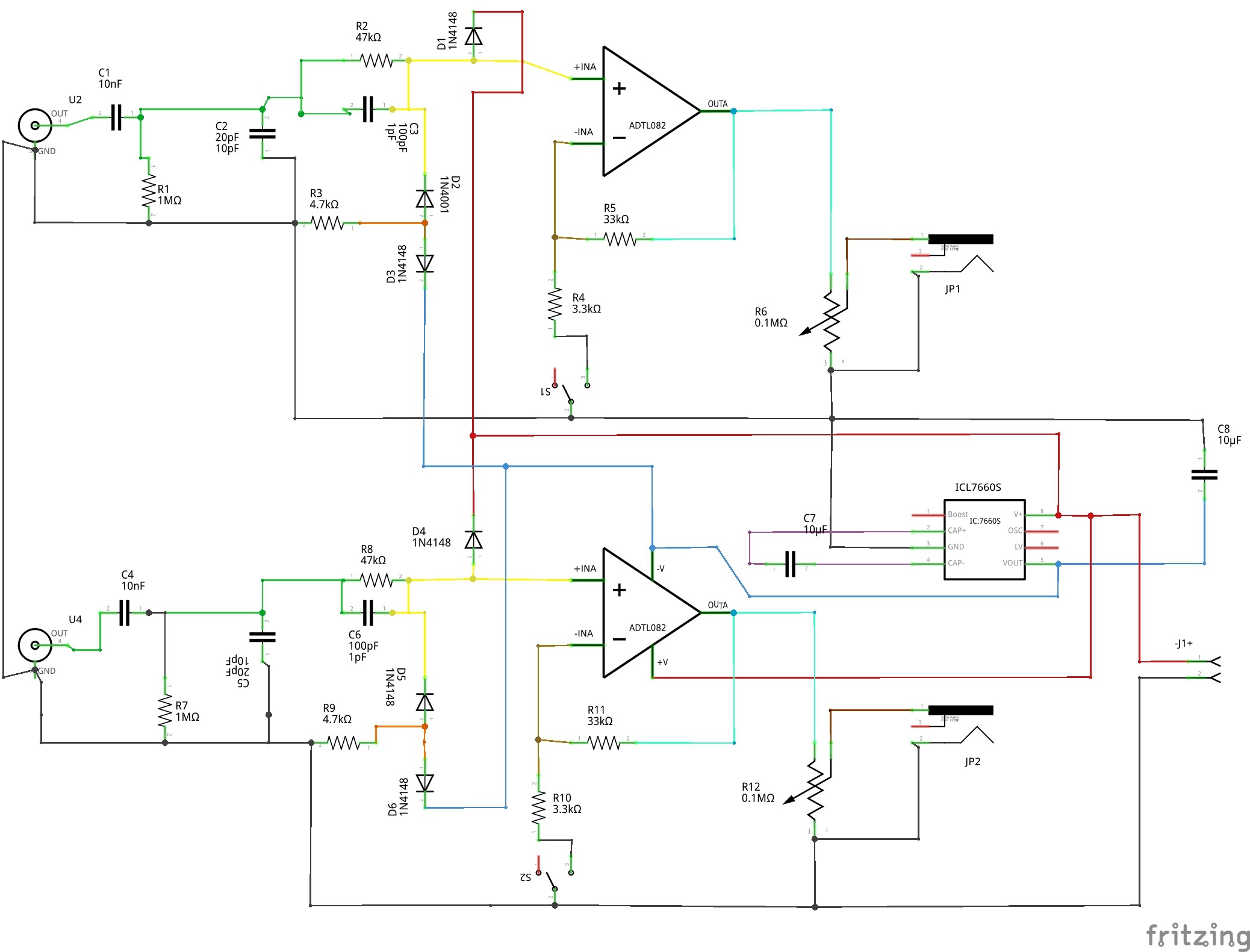
The thing is AC-coupled to begin with (see C1) so it won't show any DC component of any signal. It's not useful for measuring the majority of signals that I seem to use around Arduinos.
Looking back at the original schematic, it does say "150V protection" on it. So that section should be isolated on the PCB and no other wires should cross that section. isolate the ground plane from that section. Plus both of the 150V sections should be isolated from each other. Personally, I would not put my computer on the line when I might forget this and plug it into something more than 150V.
Is there any chance that the output RCA plugs might be plugged into some other equipment? Or accidentally contact 12V or something? Like you unplug them and let them dangle into some active circuit? Then you need protection there to ensure your circuit isn't blown up. The pot is a good protection against most errors - always turn it down less than maximum after you disconnect and stop using the thing.
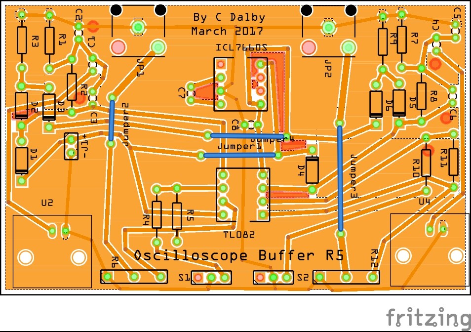
The comment on complexity mostly relates to 2-sided boards made professionally. They only charge by the square inch, not by number of holes or amount of copper, so everything you can do to make assembly easier (without making it bigger) will be free.
Speaking of holes, how are you going to mount this in a box? You don't want components with the possibility of 150V in a bare PCB strung across your desk. Mounting holes are very useful on all PCBs.
Have you heard of BitScope? I have one. I don't use it much but occasionally it's useful when I can't bring my big scope along. Their cheapest model has about the same limitations on voltage but it's much more capable.
Thanks again for your time, MorganS.
I'll try to communicate what I want to achieve.
I am at the very bottom of the arduino learning curve and continue to bite off more than I can chew.
I recently had a project where I was trying to drive a stepper motor at 0.1 rpm through to 100 rpm. I started with the stepper pot example in the ide, all good. Then went on to expand that to fit my project and I began to lose the max rpm and I wasn't sure why.
While pondering this, I thought it would be great to know whats coming out of the arduino and I happened across the xoscope site.
I quickly made up a lead with just 1m resistors on the end of the right and left channels of the mike input and instantly got usable pictures which when I rotated the pot, proved it was the serial out causing the bottleneck.

Ch1 = steps, ch2 = serial.
What a fantastically simple toy I had just come across. But I knew enough to realize that there was some inherent dangers in using the mike input the way I was and thats when I came across the buffer circuit which is the basis of this board.
Rather than build it using those preprinted development boards shown in the pictures on that page, with components boot strapped haphazardly all over the place, I thought why not extend my skills a little further and copy this circuit into fritzing and etch a custom board which surely cannot look worse than the original I was copying. (Is it)?
I also intend to 3dprint an enclosure for this with clasps to hold the board.
Then I could use xoscope with a little more confidence of not harming too much at least where xoscope was a usable option.
I also considered the plethora of cheap kit type oscilloscopes which may have been a better choice, I don't know.
One thing is for sure I, I could not justify the $150-$200 for Bitscope at this stage of my hobby.
I appreciate your words of wisdom, believe me, but I am willing to accept the apparently severe restrictions in usefulness that xoscope has at this stage at least. And no, I won't be scoping anything in the mains AC voltage range.