Hi everyone;
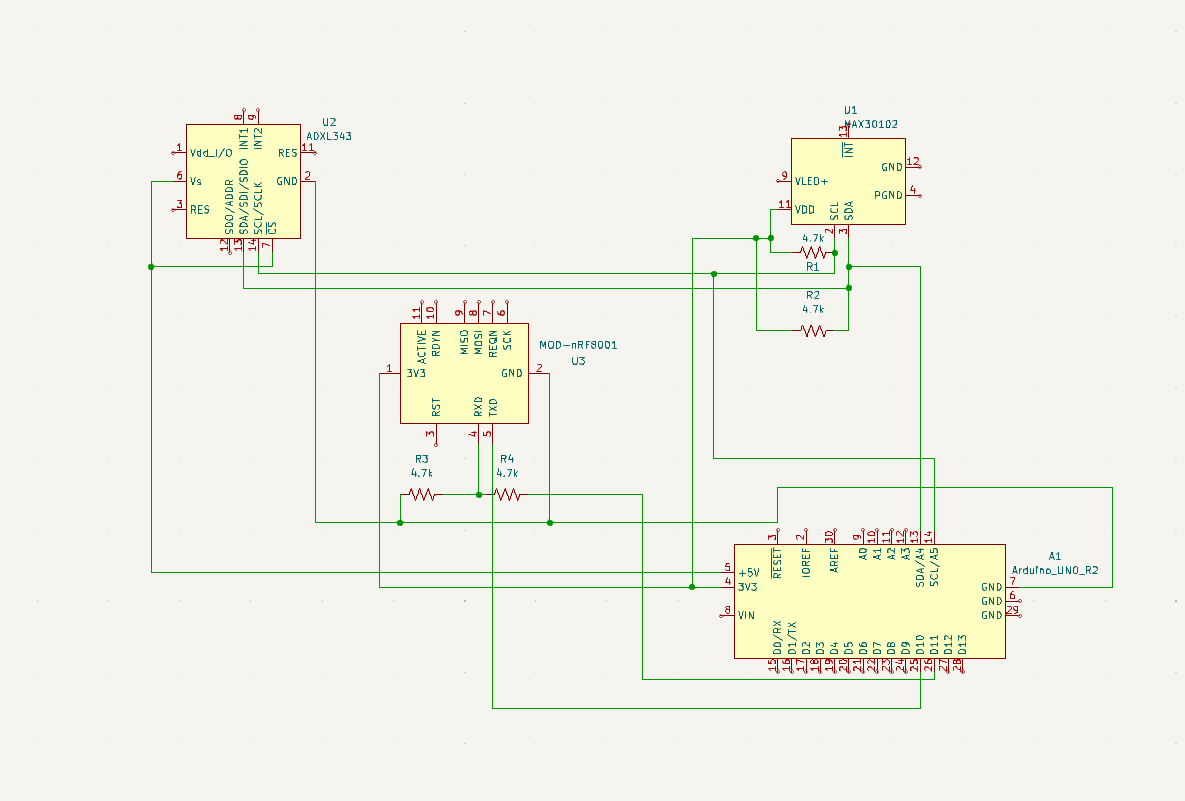
I have a project, i need to detect sleep apnea episodes with oxygen saturation, heart rate and chest movements. I'm using MAX30102 PPG sensor and ADXL345 accelerameter. I connected them like the schematic below:
Right now with the code i can initialize both sensors and bluetooth module. However, appearently I cannot get the correct data from PPG sensor. Below there is my code and output:
#include <Wire.h>
#include <MAX30105.h>
#include <Adafruit_Sensor.h>
#include <Adafruit_ADXL345_U.h>
#include <SoftwareSerial.h>
#include "spo2_algorithm.h"

SoftwareSerial BTSerial(10, 11); // RX, TX for Bluetooth module
MAX30105 particleSensor;
Adafruit_ADXL345_Unified accel = Adafruit_ADXL345_Unified(12345); // Change the address if needed

unsigned long previousMillis = 0;
const long interval = 1000;  // Sampling interval in milliseconds (adjust as needed)

void setup() {
  Serial.begin(115200);
  BTSerial.begin(9600);

  byte ledBrightness = 60; //Options: 0=Off to 255=50mA
  byte sampleAverage = 4; //Options: 1, 2, 4, 8, 16, 32
  byte ledMode = 2; //Options: 1 = Red only, 2 = Red + IR, 3 = Red + IR + Green
  byte sampleRate = 100; //Options: 50, 100, 200, 400, 800, 1000, 1600, 3200
  int pulseWidth = 411; //Options: 69, 118, 215, 411
  int adcRange = 4096; //Options: 2048, 4096, 8192, 16384


  // Initialize MAX30105 sensor
  if (!particleSensor.begin(Wire, I2C_SPEED_FAST)) {
    Serial.println("MAX30105 not found. Please check wiring/power.");
    while (1);
  }
  particleSensor.setup(ledBrightness, sampleAverage, ledMode, sampleRate, pulseWidth, adcRange); //Configure sensor with these settings

  // Initialize ADXL345 accelerometer
  if(!accel.begin()) {
    Serial.println("Could not find a valid ADXL345 sensor, check wiring!");
    while (1);
  }

  accel.setRange(ADXL345_RANGE_16_G); // Set the range to 16G

  delay(500); // Give sensors some time to stabilize
}

void loop() {
  unsigned long currentMillis = millis();
  if (currentMillis - previousMillis >= interval) {
    previousMillis = currentMillis;

    // Read IR (infrared) and Red LED values from MAX30105
    int32_t irValue = particleSensor.getIR();
    int32_t redValue = particleSensor.getRed();
    float spo2;
    float heartRate;
    float ratio = (float)redValue / (float)irValue;
    if (redValue <5000){
      spo2 = 0.00;
      heartRate = 0;
    }else{
      spo2 = 100 - (17 * ratio/100);
      heartRate = irValue / 2000.0;
    }
    // Read y-axis acceleration from ADXL345
    sensors_event_t event;
    accel.getEvent(&event);
    float accelerationZ = event.acceleration.z;

    // Print the values to the Serial Monitor
    Serial.print("IR Value: ");
    Serial.print(irValue);
    Serial.print("\t");

    Serial.print("Red Value: ");
    Serial.print(redValue);
    Serial.print("\t");

    Serial.print("SpO2: ");
    Serial.print(spo2);
    Serial.print(" %\t");

    Serial.print("Heart Rate: ");
    Serial.print(heartRate);
    Serial.print(" bpm\t");

    Serial.print("Acceleration Z: ");
    Serial.print(accelerationZ);
    Serial.println(" m/s^2");

    // Send the values over Bluetooth
    BTSerial.print("IR:");
    BTSerial.print(irValue);
    BTSerial.print(",Red:");
    BTSerial.print(redValue);
    BTSerial.print(",SpO2:");
    BTSerial.print(spo2);
    BTSerial.print(",HR:");
    BTSerial.print(heartRate);
    BTSerial.print(",AccZ:");
    BTSerial.println(accelerationZ);
  }
}

Main problem with the output is both heart rate and spo2 values are seems to be unrealistic and mostly static. I can't actually see the changes in spo2 and heart rate.
Note: Accelerameter seems to be working perfectly.
Edit 1:
This is with the example code from library. Is it possible the sensor is broken or a wiring problem.