I need help with a panel to activate practical effects for a short film shoot

Hi there

I am completely new to the world of electronics and Arduino, I have started with the purpose of facilitating the sequencing and execution of the special effects for a short film that I am making. I have some doubts about the circuit that I have designed and I would like to ask you, in case someone could give me a hand.

What I need is to create something similar to a pyrotechnic detonation panel/board to create the effect that someone has shot another person, for which I need to activate 2 systems: One of them is a solenoid valve of a pneumatic system that will propel fake blood through a tube placed inside the actor's shirt to simulate a bullet impact (what is called bullet hit squib) and the other system that I need to activate is a flash bulb that will simulate the flash of a gun.

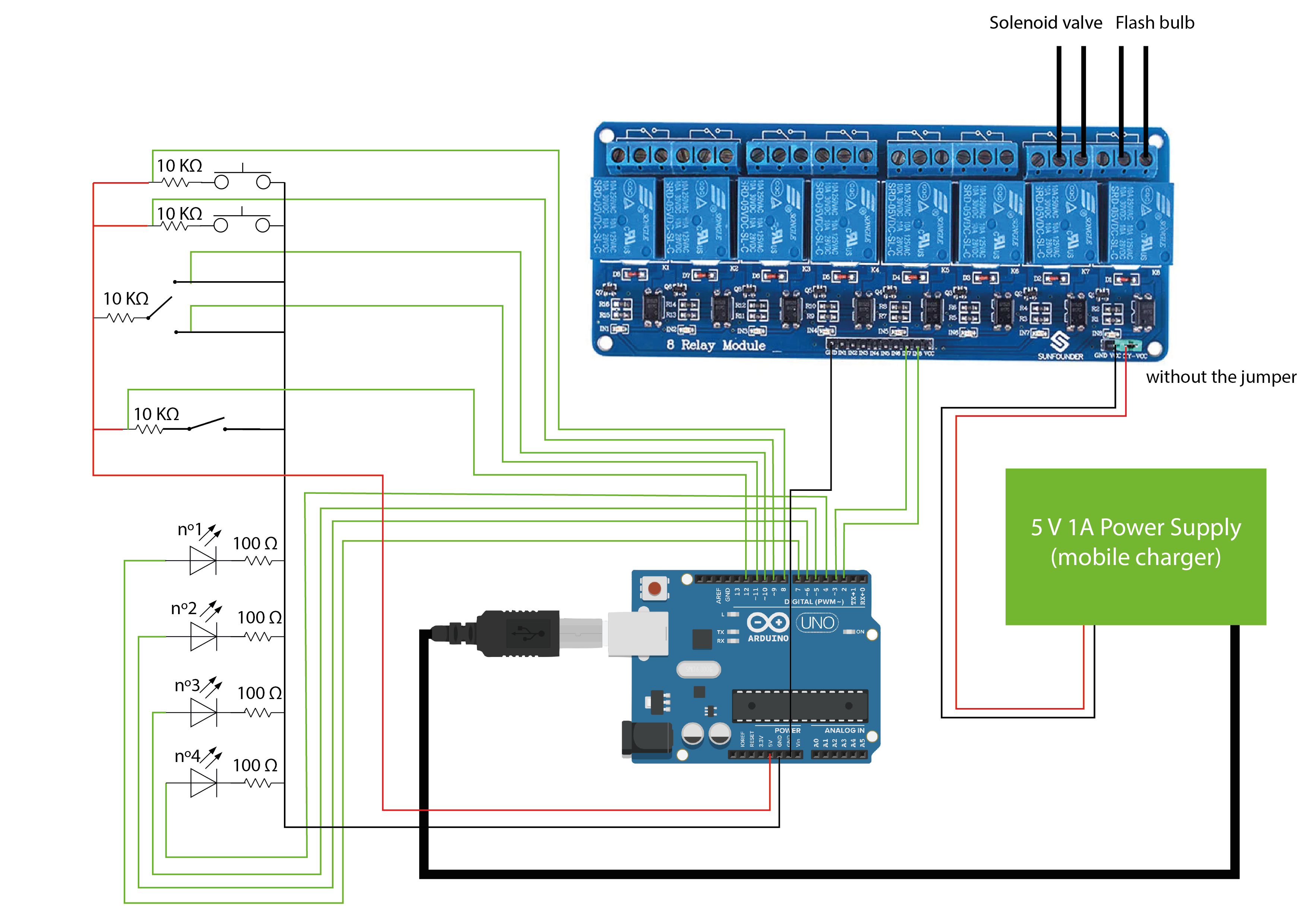
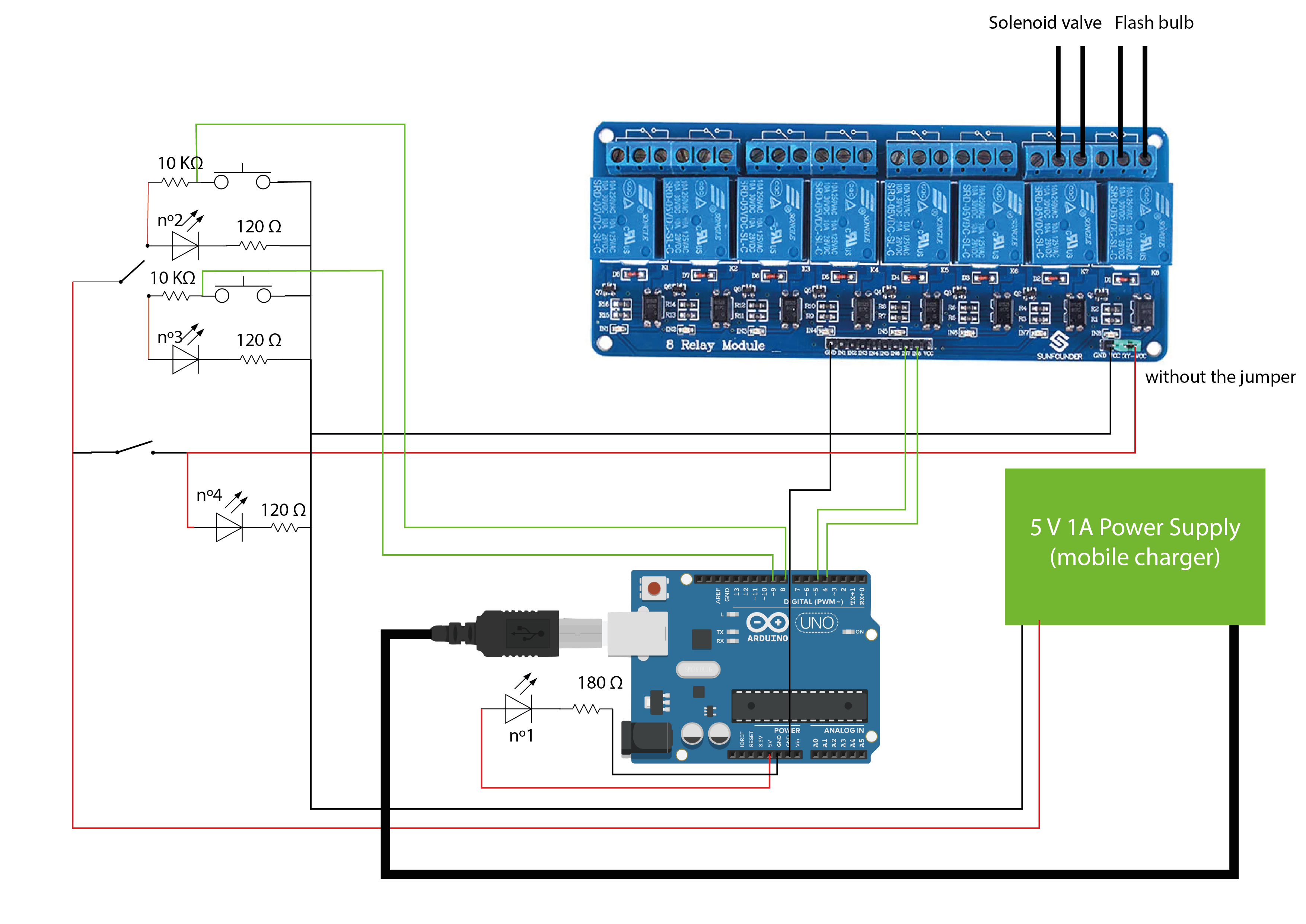
For this I have designed the following circuit, with components that I have at home, ALL the LEDs used are for the following purposes, that is why they are connected in parallel:

LED nº1: Indicates if the Arduino has power

LED nº2: Indicates that the sequence is activated from button 1

LED nº3: Indicates that the sequence is activated from button 2

LED nº4: Indicates that the system is “armed”, that is, that the relays receive power and that pressing one of the buttons will activate the sequence.

Component specifications:

LEDs

1.8V-2V 20mA

Relay module

Single relay 5V 72mA

I have tried to follow good practices by powering the module and the rest of the systems separately from the Arduino, but I have the following doubts:

Is the relay module connected well so that it receives the signal from the arduino and activates?

Is the #4 LED that indicates if the relay module is receiving power connected correctly and will it serve its purpose without shorting anything?

Do you think the resistors are well placed and their value is more or less correct for their purpose? Should I add any other resistors or any other protection elements?

In general, do you think that the circuit will function in a stable and consistent manner (regardless of programming) as required for a shoot?

To power the solenoid valve, can I connect it directly to a 12V 1A transformer without any resistance (solenoid valve specifications: 12V 540mA)?

Any other suggestions would be greatly appreciated and would be greatly appreciated.

Thank you very much in advance :slight_smile:

Please post a link to the specifications of the relay board so that the forum can check if you have connected it correctly.

Again, cannot be sure without seeing the specs of the relay board.

The 120R and 180R resistors look ok. The 10K resistors, maybe not.

I suspect it will behave unpredictably. Either pin 8 or pin 9 will be floating, depending on the switch position. Floating inputs can read HIGH or LOW at random.

Yes

Hi @PaulRB ,

I second your comments but I think the switches (although quite unusually wired) should work:

image

If the buttons are "normally closed" they connect the pin directly to GND. If not connected to 5V there is still a 10kOhm plus diode plus 120 Ohm connection to GND ...

@afirmaran1010 ,

are you using switches/buttons with built-in leds or are they separately assembled? If separately I would recommend to wire the leds and the buttons to different pins. The choice where the effect shall come from can also be done by a switch connected to a digital pin.

Here is an example how to use a switch, two buttons and two leds to solve this task:

https://wokwi.com/projects/394089604589582337

Sketch
/*
  Forum: https://forum.arduino.cc/t/i-need-help-with-a-panel-to-activate-practical-effects-for-a-short-film-shoot/1243104/2
  Wokwi: https://wokwi.com/projects/394089604589582337

  2024/04/02
  ec2021

*/

const byte ledPin1 = 12;
const byte ledPin2 =  7;

struct switchType {
  byte pin;
  byte state = HIGH;
  byte lastState = HIGH;
  unsigned long lastChange = 0;
  void init(byte aPin) {
    pin = aPin;
    pinMode(pin, INPUT_PULLUP);
  }
  boolean pressed() {
    byte actState = digitalRead(pin);
    if (actState != lastState) {
      lastChange = millis();
      lastState = actState;
    }
    if (actState != state && millis() - lastChange > 20) {
      state = actState;
      return !state;
    }
    return false;
  }
  boolean getState(){
    byte actState = digitalRead(pin);
    if (actState != lastState) {
      lastChange = millis();
      lastState = actState;
    }
    if (actState != state && millis() - lastChange > 20) {
      state = actState;
    }
    return state;
  }
};

switchType choice;
switchType effect1;
switchType effect2;

void setup() {
  Serial.begin(115200);
  choice.init(8);
  effect1.init(11);
  effect2.init(10);
  pinMode(ledPin1, OUTPUT);
  pinMode(ledPin2, OUTPUT);
}

void loop() {
  if (!choice.getState()){
    switchEffect(1);
    if (effect1.pressed()) {
      Serial.println("Effect 1 initiated");
    }
  } else {
    switchEffect(2);
    if (effect2.pressed()) {
      Serial.println("Effect 2 initiated");
    }
  }
}

void switchEffect(byte No){
  switch(No){
    case 1:
        digitalWrite(ledPin1, HIGH);
        digitalWrite(ledPin2, LOW);
      break;
    case 2:
        digitalWrite(ledPin1, LOW);
        digitalWrite(ledPin2, HIGH);
      break;  
  }
}


Hello, thank you very much for taking the time to answer

This is the link to the relay module:

https://www.amazon.es/ELEGOO-optoacoplador-Arduino-2560-1280-DSP-STM32-Raspberry/dp/B01M61VVGV/ref=asc_df_B01M61VVGV/?tag=googshopes-21&linkCode=df0&hvadid=646726966072&hvpos=&hvnetw=g&hvrand=12759931579567792688&hvpone=&hvptwo=&hvqmt=&hvdev=c&hvdvcmdl=&hvlocint=&hvlocphy=1005403&hvtargid=pla-617117652927&psc=1&mcid=8f3e9a529f9836c187a1bb8d913fb3bb

The 10KΩ resistors act as pull up resistors and they are also there because in the tests I did in Tinkercad when I pressed the button, the LED connected in parallel with said button turned off (I imagine because there is no component that consumes electricity) . after the button, the electricity “decides” to go through the entire button wire without going through the LED, sorry if I don't use the proper and precise terminology, but as I said I'm a newbie at this)

I am not sure what you are referring to exactly, the idea of the switch is to switch between two different activation systems (2 buttons), one that will be on the panel and another that will be connected with a much longer cable in case we need which was activated by the actor.

Hello, thank you very much for answering

The LEDs are separated from the buttons, I wired the LEDs, the buttons and the resistors like this to have the power supply of the Arduino and the rest of the components separated (with the exception of LED #1 since that should indicate if the Arduino is receiving power) since I saw in forums that there was a lot of insistence on That, in addition to because if I wanted to use more LEDs I would be limited to about 10, since if each one requires 20mA for 10 LEDs it would be 200mA, which I think is the maximum recommended that Arduino can deliver through the different pins.

But I think that the system you suggest (it is exactly what I needed) can work since at the moment I will only use 3 LEDs simultaneously and the power supply to the relay module will be separated.

I have redone the schematic, I have kept the 10KΩ resistors but they could really be removed using pinMode with INPUT_PULLUP. The only thing now would be to program all the functions that were previously done electrically by wiring buttons and LEDs. And the example you sent me uses a bit more complicated programming than I expected, but I'll try it anyway

If you have any suggestions on this new wiring I would greatly appreciate it.

Unfortunately that link contains no information on how the relay module should be connected.

Only one of them can act as a pull-up resistor, depending on the switch position.

I was concerned that the pin that is not connected to the switch would be floating, but @ec2021 pointed out that the 10K + led + 120R would pull the pin down, making it appear that the button was pressed.

LEDs do not require 20mA. That is the maximum and above that they can be damaged. Many LEDs will be too bright at 20mA and only a few mA are needed to see clearly if they are lit or not.

In your new diagram, one of pins 10 or 11 will be floating and could read HIGH or LOW randomly.

You do not need 2 pins to read an SPDT switch, only one is needed. Wire the common pin of the switch to ground and one of the other pins of the switch to the Arduino pin and use INPUT_PULLUP mode.

Your buttons and your STST switch are connected incorrectly and the Arduino pins will always read HIGH.

Wow, thanks for the advice, I thought it would be necessary to get as close as possible to 20mA without exceeding it, but I will follow your advice, I will use 10 mA, I imagine it will be enough, now I will have to change the resistors :sweat_smile:

It's true, I don't need to connect both pins, since they are two different states (1 and 0) I can use each one to switch between both circuits, sorry, I'm new to this

Oh, I missed it, I connected the digital pins before the resistors. In any case, I will do it as you tell me and I will connect the digital pins to the buttons and switches and the other end to GND and I will not inject the 5V (I did it this way because I saw several people do it, but if it works this other way, what do you tell me, I don't understand why they inject 5 V)

Really thank you very much for the help

They do it because they also

This topic was automatically closed 180 days after the last reply. New replies are no longer allowed.