I2C: Arduino UNO Master to Digispark ATTiny85 Slave

As the title says, I'm trying to set up I2C connection between Arduino UNO as master to Digispark ATTiny85 as slave.

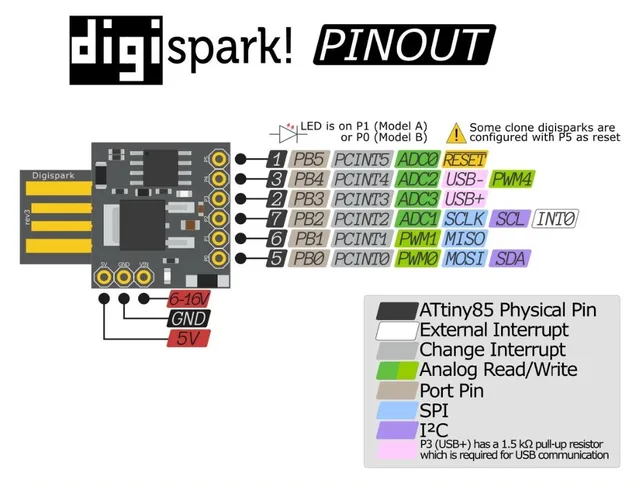
This is the device I have.

Connections:
Arduino UNO ---------> ATTiny85
Pin A5 (SCL) ---------> PB2
Pin A4 (SDA) ---------> PB0
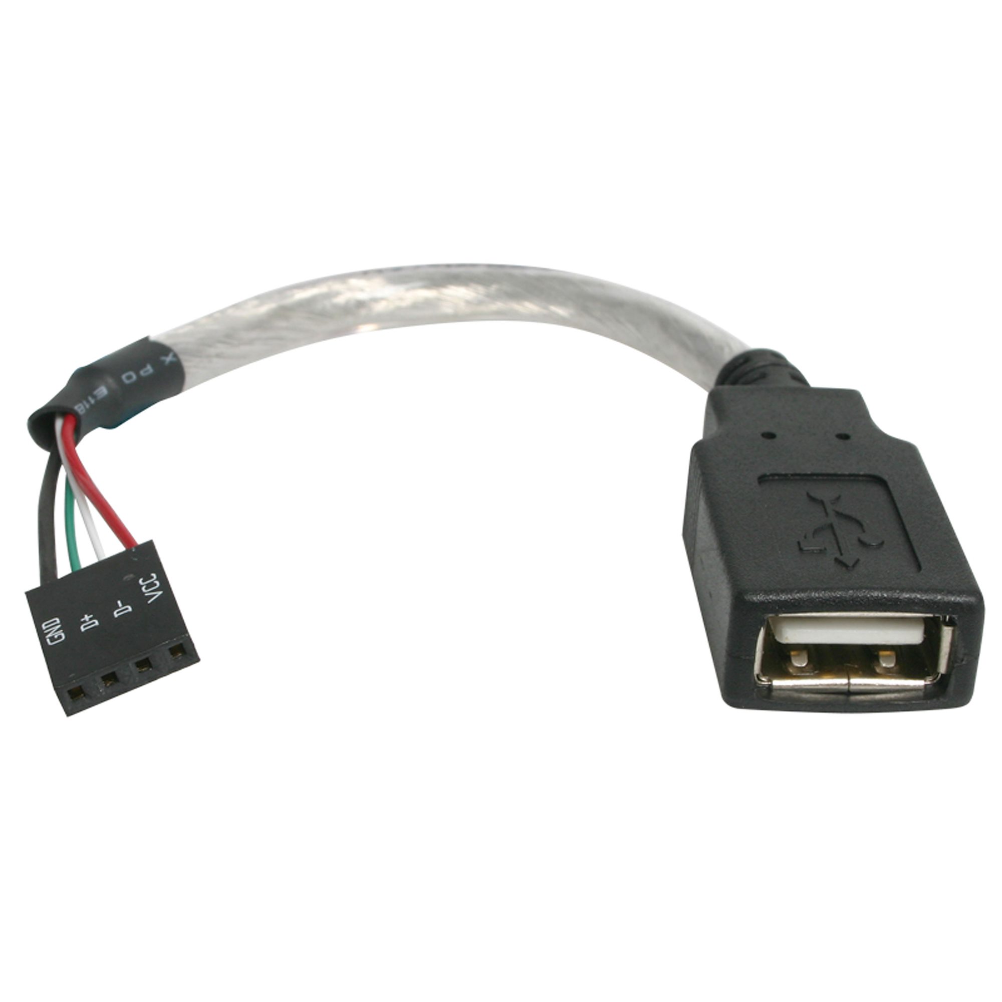
5V and GND ---------> Female usb plug to which the ATTiny is plugged into.
5.1kΩ Pull-Up Resistors on SDA to 5V.
5.1kΩ Pull-Up Resistors on SCL to 5V.

This is what I'm using for the USB connection.

Diagram:

This is the code for the Arduino:

#include <Arduino.h>
#include <Wire.h>
#include "IRremote.h"

// IR Receiver
int receiver = 13;                // Signal Pin of IR receiver to Arduino Digital Pin 13
IRrecv irrecv(receiver);          // create instance of 'irrecv'
uint32_t last_decodedRawData = 0; // variable used to store the last decodedRawData

const byte SLAVE_ADDR = 100; // ATtiny84A I2C address

void sendToATTiny(byte command)
{
    Wire.beginTransmission(SLAVE_ADDR);
    Wire.write(command);
    byte error = Wire.endTransmission();
    Serial.print("Transmission status: ");
    Serial.println(error == 0 ? "Success" : "Failed");
}

void setup()
{
    Serial.begin(9600);
    Wire.begin();

    // I2C Scanner
    Serial.println("I2C Scanner starting...");
    byte error, address;
    int nDevices = 0;

    for (address = 1; address < 127; address++)
    {
        Wire.beginTransmission(address);
        error = Wire.endTransmission();

        if (error == 0)
        {
            Serial.print("I2C device found at address 0x");
            if (address < 16)
            {
                Serial.print("0");
            }
            Serial.println(address, HEX);
            nDevices++;
        }
    }

    if (nDevices == 0)
    {
        Serial.println("No I2C devices found");
    }

    irrecv.enableIRIn(); // Start the receiver
    Serial.println("Setup complete");
}

void loop()
{
    if (irrecv.decode())
    {
        if (irrecv.decodedIRData.flags)
        {
            irrecv.decodedIRData.decodedRawData = last_decodedRawData;
        }
        Serial.print("Raw HEX: 0x");
        Serial.println(irrecv.decodedIRData.decodedRawData, HEX);
        Serial.print("Command: 0x");
        Serial.println(irrecv.decodedIRData.command, HEX);
        Serial.print("Address: 0x");
        Serial.println(irrecv.decodedIRData.address, HEX);
        Serial.println("------------------------");

        switch (irrecv.decodedIRData.decodedRawData)
        {
        case 0xF30CFF00: // Button 1 pressed
            sendToATTiny(1);
            break;
        case 0xE718FF00: // Button 2 pressed
            sendToATTiny(2);
            break;
            // Add more buttons as needed
        }

        last_decodedRawData = irrecv.decodedIRData.decodedRawData;
        irrecv.resume();
    }
}

This is for the ATTiny:

// ATTiny85 Code (Updated)
#include <Arduino.h>
#include "TinyWireS.h"

const byte SLAVE_ADDR = 0x64;
volatile byte receivedCommand = 0;
unsigned long previousMillis = 0;
byte ledState = LOW;
int interval = 0;

void setup() {
  pinMode(1, OUTPUT);
  TinyWireS.begin(SLAVE_ADDR);
  TinyWireS.onReceive(receiveEvent);
}

void loop() {
  if (receivedCommand != 0) {
    // Set interval based on command
    switch (receivedCommand) {
      case 1: interval = 1000; break; // 1-second blinks
      case 2: interval = 100;  break; // 0.1-second blinks
    }
    receivedCommand = 0; // Reset command
    previousMillis = millis(); // Reset timer
  }

  // Non-blocking blink logic
  if (interval > 0 && (millis() - previousMillis >= interval)) {
    previousMillis = millis();
    ledState = !ledState;
    digitalWrite(1, ledState);
  }
}

void receiveEvent(uint8_t numBytes) {
  if (TinyWireS.available()) {
    receivedCommand = TinyWireS.read();
    // Quick blink to acknowledge receipt
    digitalWrite(1, HIGH);
    delay(50); // Short delay (non-critical here)
    digitalWrite(1, LOW);
  }
}

These are the logs:

I2C Scanner starting...
I2C device found at address 0x64
Setup complete
I2C Scanner starting...
I2C device found at address 0x64
Setup complete
Raw HEX: 0xF30CFF00
Command: 0xC
Address: 0x0
------------------------
Transmission status: Success
Raw HEX: 0xE718FF00
Command: 0x18
Address: 0x0
------------------------
Transmission status: Success
Raw HEX: 0xE718FF00
Command: 0x18
Address: 0x0
------------------------
Transmission status: Success
Raw HEX: 0xF30CFF00
Command: 0xC
Address: 0x0

But the led on the Digispark Attiny doesn't blink (I tested that same code on the tiny without the counditionals and it does blink as intended)

  1. Do I require the pullup resistors for this set up?
  2. Am I missing anything else?
  3. Any other suggestions?

What is this? If it is pu8ll up resistors where do they go? A simple schematic would be much easier to follow.

I tried out a stripped down version (no IR remote, just Serial keys 1 & 2). Programmed the 85 fuses for 8MHz internal, put a 4.7K pullup on pin 1 (reset), took the delay out of receiveEvent and changed numBytes from uint8_t to int to keep the compiler happy.

With everything programmed and hooked up, pressing 1 in the serial monitor gets a slow blink from the 85, and pressing 2 gets a fast blink.

Put the delay back into receiveEvent and it continued to work.

Seems fine to me.

@gilshultz
yes, sorry I meant resistors. I'll make a diagram and upload it.

Diagram added. thanks!

@van_der_decken
hey thanks! Could you share the code please?
Also, I added a diagram, could you tell me if that looks ok to you?

@totofefe
Use cable of Fig-1 instead of Fig-2 to connect Digispark Board with PC.


Figure-1:


Figure-2:

1. Create sketches for both Master and Slave (ATtiny85) so that when 0x1234 goes to Slave, the onboard LED of Slave (ATtiny85) will turn on.
... pending.

2. Create sketches for both Master and Slave so that the Slave will send 0x5676 to Master when the Master makes a request to the Slave.
... pending

@GolamMostafa
To be clear: I'm not having any issues loading sketches to the attiny. I've already done this with a dongle similar to Figure 1. Tested the blinking of led and everything worked fine.

Figure 2 is what I use to provide power from Arduino Uno when everything is loaded and want to work without the computer.

  1. This is what I've already shown in the code I provided, isn't it? What do you mean by ...pending?
  2. Good idea. I'll do this to confirm if Slave is actually recieving the request or not. Question: is 0x5676 a random number or did you choose this address specifically for some reason?

It means that I will be providing the tested codes if requested.

It is just a known number which the Slave will send to Master if Master makes a request.

@GolamMostafa
Ah awesome yes! If you can share the code that would be amazing. Thanks!

You can't seriously think people keep every scrap of one-off test code. I wired it, I wrote it, I tested it. It worked. I took it apart, I deleted it.

1. The Hardware Setup.

UNO           ATtiny85
SDA (A4)      SDA (PB0)
SCL (A5)      SCL (PB2)
GND           GND
              PB1  -----> onBoard LED

2. Uplaod the following tested Sketch into Master-UNO.

#include<Wire.h>
#define slaveAddress 0x23

void setup()
{
  Serial.begin(9600);
  Wire.begin();
  //--------------------
  Wire.beginTransmission(slaveAddress);
  byte busStatus = Wire.endTransmission();
  if (busStatus != 0)
  {
    Serial.println("Slave is not found.");
    while (true); //wait for ever
  }
  Serial.println("Slave is found.");
}

void loop()
{
  Wire.beginTransmission(slaveAddress);
  Wire.write(0x12);
  Wire.write(0x34);
  Wire.endTransmission();
  //-----------------------
  delay(2000);
  //------------------------
  Wire.requestFrom(slaveAddress, 2);
  int y = Wire.read() << 8 | Wire.read();
  Serial.print("Data received fromm Slave: ");
  Serial.println(y, HEX);//shows: 5676
  delay(2000);
}

3. Upload the following tested Sketch into ATtiny85.

#include<Wire.h>
#define slaveAddress 0x23
#define led 1
volatile bool flag = false;
int y;

void setup()
{
  Wire.begin(slaveAddress);
  Wire.onReceive(receiveEvent);
  Wire.onRequest(sendEvent);
  pinMode(led, OUTPUT);
}

void loop()
{
  if (flag == true)
  {
    for (int i = 0; i < 2; i++)
    {
      digitalWrite(led, HIGH);
      delay(250);
      digitalWrite(led, LOW);
      delay(250);
    }
    flag = false;
  }
}

void receiveEvent(int howMany)
{
  int y = Wire.read() << 8 | Wire.read();
  if (y == 0x1234)
  {
    flag = true;
  }
}

void sendEvent()
{
  Wire.write(0x56);
  Wire.write(0x76);
}

4. Open Serial Monitor of UNO at Bd = 9600.
5. Check that the following message appears on the Serial Monitor.

Data received fromm Slave: 5676

6. Check that onBoard LED of ATtiny85 of Digispark Board blinks for two times. It will happen when I2C-Slave receives 0x1234 from I2C-Master.

@GolamMostafa
you're the best. I'll let you know as soon as I test this. Thanks!

@GolamMostafa this works perfectly! thank you so much!