I2C DS1307 RTC Clock weird problem, aka "2165-165-165..." output

Hi all,

I have a weird problem with a DS1307 I2C Clock module, I'm an Arduino newbie and I hope some specialists here can help

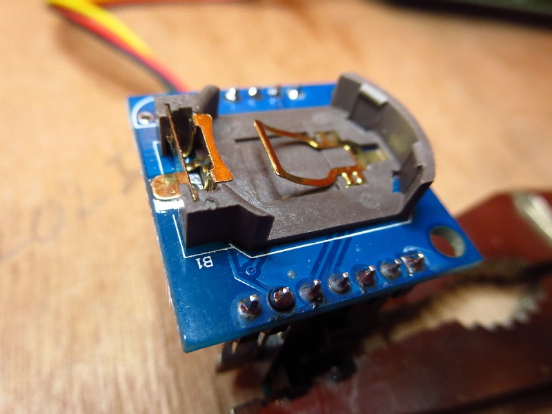
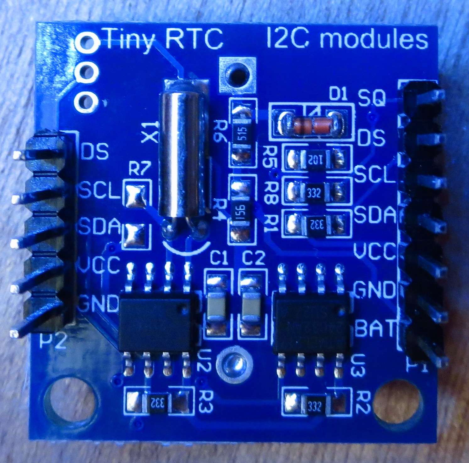
Here is a pic of the RTC if it can help:

I used the connections, the sample code and the library from this page:

Everything worked fine for a few hours...

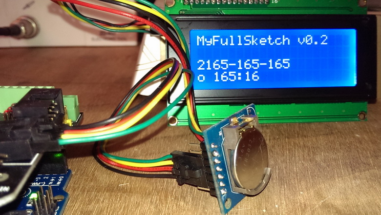
Then the RTC started sending weird output like:
RTC date: 2165-165-165 Mo time: 165:165:85

When this happens I can no longer set the clock, neither change the NVRAM content

After searching on the web I found the two main reasons for this problem can be a bad I2C connection or a battery overvoltage

My connections seems fine, so I checked the backup battery voltage and it measured at 3.94V ! In fact it is a LIR2032 3.6V rechargeable Li-ion battery.

I removed the battery and then the clock worked fine again !

Then I tried putting a CR2032 3V Lithium battery, and the same problem was back...

If I remove again this battery the clocks works fine again

So, I thought the problem came from the provided battery overvoltage, and I thought putting a 3V CR2032 battery would fix the issue, but sadly nope

Any idea where the problem comes from an how to fix it ?

Thanks in advance for your kind help

I read somewhere that sometimes the battery cell holder shorts somewhere, like the effects you describe. Check out if the pins of the holder are not bent.

Thanks RobvdVeer for the suggestion

I carefuly checked and it doesn't seems this can be the issue

Here is a close view of the battery holder:

EDIT:

I made some more tests:

  • without the backup battery in the RTC, I set my clock to the correct date/time, then I put in place the LIR2032 battery, the clock keeps runnin fine:

I think this excludes any short/bad contact problem

  • leaving the battery in place, I unplugged and plugged back my arduino, the glitch is back:

So it seems that the clock gets stuck when powered by the backup battery

Weird

Is the battery of the correct voltage?

What if you use the sample code that comes with arduino? Does that make a difference? I'm just guessing here.

Thanks for these suggestions

Well, according to what I found on the web the battery correct voltage is 3 to 3.3V

The RTC came with a LIR2032, wich is a 3.6V rechargeable Li-Ion battery. And I measured it's voltage at 3.98V! Some people reported the same problem with a 3.6V battery, and they fixed it by putting a 3V battery. So I thought I found the problem, but putting in a CR2032 battery which is a 3V battery doesn't fix the issue, so I'm really lost here

I don't think it could be a code problem, otherwise the clock wouldn't work at all. In fact after the last tests, we can say the clock gets stuck when (equiped with battery AND disconnected from +5V)

And the Arduino doesn't comes with the needed library (DS1307new.h)

Measure the battery when it's connected to a load, an i'm sure it'll drop below 3.98v.

I'm out of suggestions to be honest, either the 1307 is faulty, or something weird happens when synchronising, as it is not a battery issue as you say.

Did you try another unit?

Well, I see no explanation either, I guess the unit is faulty.

I orderer two different DS3231 I2C Clocks (they are more accurate than the DS1307), this should fix my issue :stuck_out_tongue:

Thanks RobvdVeer pour your kind help !

Ironicly i've just replaced my ds3231 break outboard by a ultra low-cost ds1302 dip ic, for testing purposes. Doesn't do i2c or spi, it has a horrible 3-wire interface, i don't know how accurate it is, but if it is acceptable, i can drop the i2c library from my project and have one less smd chip to worry about...

RobvdVeer:
Ironicly i've just replaced my ds3231 break outboard by a ultra low-cost ds1302 dip ic

haha that's quite funny ideed ^^

Thank you so much!! We finaly remove the 2165-165-165 output ect..

We simply remove the CMOS Battery with only 3.1V output and we tap the 3.3V on Arduino Uno to the pin 3 of the DS1307. By browsing same problem and here i merge it and work fine now..

1 Like

Philgood:
Thanks RobvdVeer for the suggestion

I carefuly checked and it doesn't seems this can be the issue

Here is a close view of the battery holder:

EDIT:

I made some more tests:

  • without the backup battery in the RTC, I set my clock to the correct date/time, then I put in place the LIR2032 battery, the clock keeps runnin fine:

I think this excludes any short/bad contact problem

  • leaving the battery in place, I unplugged and plugged back my arduino, the glitch is back:

So it seems that the clock gets stuck when powered by the backup battery

Weird

hi. please check the -ve below the battery holder. Desolder the battery holder and then resolder again. i'm doing like that and my problem is solve.

This reply doesn't solve the original problem but it may provide some clues.

I also had this very same problem with the only lines of output being:
2165/165/165 165:165:85
I found that my I2c was plugged into the incorrect pins as different google images of pinouts show different pins for I2c on the Nano (it should be A4 and A5).

As I had read this thread in hope of an answer I thought I would add some results from a little bit of experimentation.

If either of these I2c pins are not connected on their correct pin it gives the same tell tale output of 2165/165/165 165:165:85

If there is no battery and you disconnect 5v it stops transmitting (obviously)

If there is no battery and you disconnect just Gnd it transmits an output of 2000/1/1 0:0:0

If you have no battery but 5v and Gnd are connected it works just fine!

Having the same issue, just coping and past my answer to stackoverflow, please send me your thoughts?

up vote
0
down vote
Having the same problem here, it turns out that the DS3231 communication can get unsynchronised with the microcontroller due to different events. Seems like the cryptic output is coming from that, at least here debugging with a DS3231 connected to an ESP8266 Arduino.

Following the datasheet specification:

The I2C interface is accessible whenever either VCC or VBAT is at a valid level. If a microcontroller connected to the DS3231 resets because of a loss of VCC or other event, it is possible that the microcontroller and DS3231 I2C communications could become unsynchronized, e.g., the microcontroller resets while reading data from the DS3231. When the microcontroller resets, the DS3231 I2C interface may be placed into a known state by toggling SCL until SDA is observed to be at a high level. At that point the microcontroller should pull SDA low while SCL is high, generating a START condition.

And inspired on their official application note 3506

Using the ESP8266 and using their I2C implementation. You can get macros functions on how to access the SDA and SCL pins bitwise. Here is one implemented reset function based on the official example for the 8051.

#define SDA_LOW()   (GPES = (1 << SDA))
#define SDA_HIGH()  (GPEC = (1 << SDA)) 
#define SCL_LOW()   (GPES = (1 << SCL))
#define SCL_HIGH()  (GPEC = (1 << SCL))
#define SDA_READ()  ((GPI & (1 << SDA)) != 0)

void resetRTC() {

 pinMode(SDA, INPUT_PULLUP);
 pinMode(SCL, INPUT_PULLUP);
 do {
   SDA_HIGH();
   SCL_HIGH();
   if (SDA_READ()) {
     SDA_LOW();
     SDA_HIGH();
   }
   SCL_LOW();
 } while (SDA_READ() == 0);

}

This is working fine and seems to solve the problem

A more simple solution would be calling Wire.status(), it also seems to work.

I'm not sure if for all cases. This method is doing checks for status and for one case it calls twi_write_start() which has some similarities with the function resetRTC() above.

In case you want to implement a similar function for that ATMEL Arduino you will need to look into the bitwise implementation to manipulate SDA and SCL on Arduino I2C core.

this is the same question on StackOverflow

The solution to this problem is to use a non-rechargeable battery cr2032 and cut the track that connects the 5v power with the "battery".

Not necessarily. The solution depends on what the problem is, which can be the result of several different power issues.

A newbie can encounter this by simply adding a 16x2 LCD display after having time on the serial monitor, thereby suggesting the villain is the LCD backlight. It isn't, it is simply the trigger, and the real villain is inadequate power from the PC USB socket. In this event, the real solution is to use a 9v wall wart, and DS1307 is entirely innocent.

1 Like

Hi there, I got the same problem with "165:165:85" and here is my finding:
Using the UNO board there is no connection between A4/A5 to the signals SDA/SCL! It obviously exists on other boards like the Aduino DUE but not on UNO and this is the culprit.
I connected to the native SDA/SCL Pins near the AREF Pin (on UNO R3) to the RTC DS1307 and it works. The numbers "165:165:85" come (my opinion) from the floating state of the Pins A4 and A5, which are not "pinmode'd" i.e. they are not physically connected/configured to be SDA/SCL.
I found no info about configuring the UNO R3 board to have SDA/SCL on analog pins A4 + A5.
I have a temp/Datalogger shield and have to delete the connections to A4 /A5 and reconnect them from the DS1307 to the SDA/SCL pins on the R3 board and - after 2 days of investigations in libraries - the RTC immediately works with no other change than re-wiring. I have the IDE 1.8.7 running with wire.h and RTClib.h included. Hope this helps.

mischa54:
Using the UNO board there is no connection between A4/A5 to the signals SDA/SCL! It obviously exists on other boards like the Aduino DUE but not on UNO

Well, that's a first, a Uno R3 that is manifestly non-compliant with factory specification. Does that happen often?

mischa54:
Using the UNO board there is no connection between A4/A5 to the signals SDA/SCL!

I've just checked my arduino.org Uno R3 with a multimeter. A4 and A5 are definitely connected to the corresponding I2C pins near ARef (as expected).

Pins A4 and A5, are not physically connected/configured to be SDA/SCL.

If this is true, the I would return the unit to the vendor as defective. Where did this "UNO" come from?

I know this is an old post, but I have a strong suspicion for others reading this what is causing the 2165-165-165 issue. That number is generated in the Adafruit library when it is not communicating via i2C to the DS1307. You literally could disconnect the DS1307 and get the same result. IMO, the most likely issue is that the backup-battery voltage and the input voltage are too close to each other.

From the DS1307 Datasheet: emphasis mine

The nominal power-fail trip point (VPF) voltage at which access to the RTC and user RAM is denied is set by the internal circuitry as 1.25 x VBAT nominal. A lithium battery with 48mAh or greater will back up the DS1307 for more than 10 years in the absence of power at +25°C.

So if you try to power your Arduino from 3.3V and the backup battery is 3ish volts you fall into the lockout window of the DS1307. The DS1307 essentially treats the situation as a power fail and goes into long term storage on battery only. Run the Arduino off of 5v and make sure your wiring is such that:

  1. the backup battery is only connected to GND and VBatt
  2. VCC of the DS1307 is connected to a voltage that is at least 1.25 times the backup battery voltage. (5v from your arduino)

I spent hours learning this the hard way.

Bad pullup resistors may also cause the problem, but thats a long shot.