Hello! I’m trying to connect 14 TLV493D-A1B6 sensors to an Arduino UNO R4 WIFI via the SCL and SDA lines. According to the datasheet, up to 8 of them can be connected at once with exclusive supply lines so that they can be assigned different addresses on start. Since this wouldn’t really work for my use-case, I opted to try to use two TCA9548APWR I2C multiplexers in order to control the 14 different sensors. I used KiCad to make the following circuit:
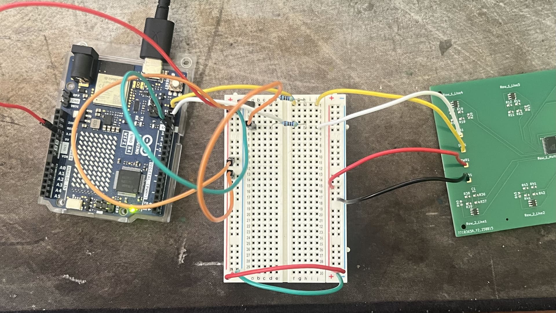
Unfortunately, after getting the PCB, I realized that I had forgotten to add pull-up resistors to the SCL and SDA lines from the TCA9548APWR multiplexers, meaning that I had to add a breadboard to my circuit as so:
In order to test the I2C line, I ran the following I2C Scanner code found online:
#include <Wire.h>

#define WIRE Wire

void setup() {
  WIRE.begin();

  Serial.begin(9600);
  while (!Serial)
    delay(10);
  Serial.println("\nI2C Scanner");
}

void loop() {
  byte error, address;
  int nDevices;

  Serial.println("Scanning...");

  nDevices = 0;
  for (address = 1; address < 127; address++) {
    WIRE.beginTransmission(address);
    error = WIRE.endTransmission();

    if (error == 0) {
      Serial.print("I2C device found at address 0x");
      if (address < 16)
        Serial.print("0");
      Serial.print(address, HEX);
      Serial.println("  !");

      nDevices++;
    } else if (error == 4) {
      Serial.print("Unknown error at address 0x");
      if (address < 16)
        Serial.print("0");
      Serial.println(address, HEX);
    }
  }
  if (nDevices == 0)
    Serial.println("No I2C devices found\n");
  else
    Serial.println("done\n");

  delay(5000);
}
When I run this code, it returns “No I2C devices found.” I don’t expect it to find the 14 sensors behind the multiplexers, but shouldn’t it detect the multiplexers? What am I doing wrong?
Hopefully that's just the topside view on the photo, but when looking at the pair of wires at the bottom of the photo, the right hand side of the breadboard looks like it has the polarity reversed?
Bear in mind that the maximum current that can be drawn from the 3.3V line on the R4 is 50mA. Each multiplexer can draw up to 100mA.
The other observation is that you might want to have a current limiting resistor between VCC and A0 to pull up and provide address 1 on the second multiplexer. A 4.7k will be fine if you already have those spare, but a 10k should also do nicely.
I double-checked, it’s just the way the photo looks, the positive and negative on the breadboard are wired correctly.
Wouldn’t the maximum current from the 3.3V line on the R4 come from the SGM2205-3.3XKC3G/TR? The datasheet for that says it can supply an output current of 800mA.
EDIT
The 3v3 pin can handle more, but the safe level is only 200ma; the spec says 500, but there are already draws on it, so stick with the safe value. With two multiplexors, you will likely already encounter a problem.
If you can turn off the ESP32 on the R4 you will gain about 150ma or more.
Yes, 500ma is maximum but the esp32 uses a chunk and it will not be 500 if the USB/5V power wastes some in heat and if the source is not capabe of creating the entire 500ma to begin with.
In your schematic the address pins of the first TCA9548APWR are all floating, and only A0 of the second one is connected to anything. You need to connect all the inputs to either 0V or Vcc to define the address.
Similarly you have also left not reset floating. Check the data sheet for recommendations for reset. My guess (I've not read the data sheet) would be something like a 10k to 100k resistor from not reset to Vcc and a 0u1F capacitor to 0V.
Not connected does not equal logic zero.
Edit
I just read that @david_2018 has made a similar comment.
As pointed out the three address pins need to have a defined state of VCC or GND to set the address.
Connecting A0 / 1 / 2 to GND on the first multiplexer will set it to address 0x70 ,
Connecting A0 to VCC ( Done already ) and A1 / 2 to ground on second multiplexer will set it to address 0x71
A0 / 1 / 2 are directly connected as per datasheet, no series resistor.
Based on A0 is connected to VCC on second multiplexer Id assume that was the address setup you intended to aim for.
Reset as pointed out needs to be pulled to VCC via a pull up - I used 10K in my case without issue.
Happy to be corrected, but the information about the multiplexer current is in the datasheet and is a maximum. From the comments above I accept that the information about the 3.3V line is wrong. I need to be more careful when I do online research. The regulator itself is capable of much more than that.