I am running into an issue communicating with a adafruit DS3231 precision breakout board from both an uno and a pro mini.
At the moment my question is not so much looking for help to solve the problem as much as my determining if I need to go further down one route.
I have a sketch that is reading the sensor every 2 seconds and it works fine for dozens for times thru the loop. Then it will not work for anywhere from 1 to several dozens of times, then it will start working again.
Sometimes it works but the data is garbled (as if it missed a bit or two).
My question regards the voltage levels. I have a scope and can capture the signals and even decode the i2c. What ever is happening is happing on the scope in spy mode as well. my Vcc is 5V dead on. My SDA and SCL lines are 3.65V. My understanding is they should be .7% of VCC so 3.5V. Which makes me wonder if the .15V additional is allowing it to work sometime and not in others.
I made a custom pcb but it does this both on the pub and on a bread board.
Should I try and put resistors on to drop the SDA/SCL lines to 3.5 or would that be a waste of time as it should not pose and issue and move on to more complicated things like capacitance?
greglwood:
my Vcc is 5V dead on. My SDA and SCL lines are 3.65V.
Are you supplying 5 V to the Vin pin of the DS3231 module?
greglwood:
My understanding is they should be .7% of VCC so 3.5V.
This is the minimum value for both the DS3231 and the ATmega328P on your Uno/Pro Mini.
greglwood:
Should I try and put resistors on to drop the SDA/SCL lines to 3.5 or would that be a waste of time
That would be a waste of time and could actually be harmful. 3.5 V is the minimum and running right at the minimum is not a good thing. Being above the minimum at 3.65 is a better situation.
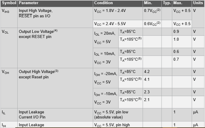
When the ATmega328P is running from Vcc supply of the range: 2.4V to 5.5V, the minimum VIH that will be reliably recognized as logic HIGH is 3.0V (0.6*5) for 5V supply at Vcc-pin .
pert:
That would be a waste of time and could actually be harmful. 3.5 V is the minimum and running right at the minimum is not a good thing. Being above the minimum at 3.65 is a better situation.
Why is it concerned to operate the circuit much above the minimum level of VIH (3.0V)? This is related with 'Noise Margin' of the digital circuit/gate. When a source signal (it is 3.5V in your case -- the OP) drives a destination, it picks up 'road noise' or 'environmental noise'. When the signal arrives at the destination (the driven gate), it might add negative noise of 0.6V (600 mV); as a result the signal becomes 3.5 - 0.6 = 2.9V which is below the minimum requirement of 3.0V and the circuit will malfunction as 2.9V will not be recognized as logic HIGH. Therefore, the noise margin of the circuit must be improved. The noise margin is improved when the the driving signal does not go below VOH (4.2V, Fig-2). Now, the noise margin for the same -0.6V noise is: 4.2 - 0.6 = 3.6V which is much higher than VIH (3.0V, Fig-1). So, check why the SDA/SCL signals are at so lower level of 3.5V.
GolamMostafa:
When the ATmega328P is running from Vcc supply of the range: 2.4V to 5.5V, the minimum VIH that will be reliably recognized as logic HIGH is 3.0V (0.6*5) for 5V supply at Vcc-pin .
You're right. I must have been thinking of the ATmega4809. Thanks for the correction.
All,
Thanks for the replies. I am supplying from the arduino's 5v pin. I was thinking about this backwards as I had the scopes triggering in mind and the voltage dropping below the max. Newbie leaning on my own stupid mistake because i really did no better.
I have not figured out how to make the scope trigger without using an i2c logic trigger (which misses it too) so I am not seeing anything when the data is missed or missing bits. I do see the arduino's request fly be when scope is in realtime but it's so fast I can see anything except that fact the pattern when by. I can't real tell the levels, or if any spikes/noise are present at that given time.
I'll figure the scope out so I can see what's going on at the time of failure but the noise explanation was great and I understand it much better that what I've read from other source. I'm going boost the Voltage on the two lines and see if all starts working correct, but even if it does I want to see it on the scope failing. For me this is about learning no so much trying to complete a project.
If you are using Arduino UNO, please carry out the following simple experiments and report the results:
1. Connect 2x2.2k or 2x4.7k pull-up resistors with the SDA and SCL lines of UNO. 2. Do not connect any load with I2C Bus -- I mean leave them open. 3. Upload the following test sketch.
4. Measure DC voltage levels at SDA and SCL lines at UNO end using Digital Volt Meter. Report the values. I will compare your results with mine one.
5. Also, check the signal levels at both SDA and SCL lines using scope; draw a rough sketch of the wave shapes and post it. I will compare your results with mine one.
6. Please, connect an I2C LCD with the I2C Bus of UNO and repeat Steps-4, 5 at UNO side and LCD side. (Assume you have connected LCD with UNO using jumper wires).