I'm misapplying Ohm's Law, need correction

I'm just a beginner, and though I knew Ohm's Law in high school, I never really knew what it was for, how and why you'd use it. So as I'm starting to work with the Arduino and simple circuits, there's some crucial piece I'm missing in my thinking. Here's my dilemma:

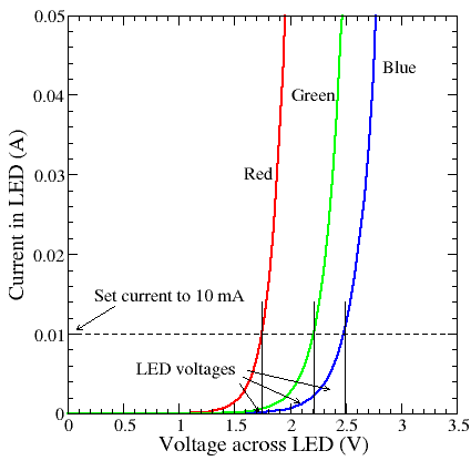
I'm having fun messing about with LEDs. From a PWM digital pin to a 220 Ohm resistor to a red LED and back to ground. Easy, right? I even understand (I think) the reason why it is this way: The LED doesn't use up all of the voltage being sent, so without a resistor to use up the rest, you'll blow the LED. 5V minus LED forward voltage of 1.8V equals 3.2V; wanting to throw 20 mA at it; plug those into the equation for Ohm's Law, turn it around and solve it means you need 160 Ohms of resistance to balance the circuit; 220 Ohms is the next step up that I have in my kit, so it can take a little more voltage than is sent, so it's a safe circuit and the LED will light at not quite full brightness. Okay, I get that. And with the blue LED I have, the forward voltage is 2.8V, so it would only need 110 Ohms resistance, but since 220 is still the nearest (above) that I have, I use the same one--but it doesn't need as much.

So that got me thinking (and thinking is where I went wrong, obviously)--if the needed voltage were high enough, you wouldn't need a resistor at all. LEDs wired in series means their forward voltage is added together (right?). Vf 1.8V * 3 = 5.4V, so voltage from a 5V pin would be fine and safe, should light all three LEDs at a little less than full brightness, without using a resistor. Well, that was my amateur thinking, anyway.

I wanted to light as many LEDs as I could, but since I had eight red LEDs and had made this design to use three, I just wired up two such circuits. Each was from a digital pin to one LED, series to another, to another, and back to ground. To wire two of these circuits simply, I wired the Arduino pins to the rails of a breadboard and each circuit to those rails, so both sets were drawing from the same 5V pin in the first iteration. I suspected the LEDs wouldn't be as bright as if they were on separate pins, but this was the first, simplest go-round. I set up a simple program to just send output voltage to the pin, like the Blink sketch without the blinking.

One set of LEDs didn't light (perceptibly, at least) at all, and the other set were dim. I switched some of the LEDs around, including from one circuit to the other, and still got the same result (that was in case one was wired backward, or one had burned out or something).

So I rewired the circuits so that each set of three LEDs was fed by a separate pin from the Arduino, but I got exactly the same result. Tried reversing the pins, tried different pins, same.

Using an Arduino Uno R3. Have tested the LED forward voltage with a multimeter, on several (if not all) of the LEDs when they were wired individually. I have checked the wiring several times over, including completely dismantling the circuit and rebuilding it from scratch.

  1. Why would these two circuits, exactly the same in parallel, work differently? That is, I get that I've done something wrong and a set of three wired this way won't light as I'd intended, but why wouldn't two identical sets of three work (or not work) the same as each other?

  2. Why does my (apparent) result end up the same whether both circuits are fed from one Arduino pin or each from a separate one? Instinct told me that with both sets sharing from one pin, they might be half as bright as with each set from a separate pin, but both wirings gave me the same result.

and of course, the main question:

  1. What about current am I forgetting, overlooking or misunderstanding in my design of the three-LED circuit in the first place? How do I figure how much current each LED is being given? I know that my thoughts about "just closely match the forward voltage to the battery voltage and you're good" were wrong, but why was I wrong? In applying Ohm's Law to this, starting with battery voltage minus combined LED forward voltage results in -0.4V, so I had no idea how to apply the equation.

f the needed voltage were high enough, you wouldn't need a resistor at all. LEDs wired in series means their forward voltage is added together (right?). Vf 1.8V * 3 = 5.4V, so voltage from a 5V pin would be fine and safe, should light all three LEDs at a little less than full brightness, without using a resistor. Well, that was my amateur thinking, anyway.

Where you went wrong is not understanding how an LED works. Unless the LED has enough voltage across it then no light will be produced. Therefore if two LEDs in series add up to more than the supply you will get nothing or very dim, depending on the leakage current.

Having no resistor in an LED circuit is a very bad idea because the voltage / current relationship of an LED is non linear, and a small increase in voltage can have a vast increase in current. Ohms law works for the resistor but not for the LED.
Read this:-
http://www.thebox.myzen.co.uk/Tutorial/LEDs.html

For a simple component (something you can model as having a positive and a negative side, which you put current through to do something), consider if you connected the supply at 0v, and slowly ramped up the voltage (magically holding everything else constant), and graphed the current as a function of supply.

This is called an I-V curve.

For a resistor, it's a straight line (ohm's law)

For an LED, it's... well, I pulled this one from google. There are lots more, and the exact point at which it shoots up depends on the manufacturing process, but:

Now watts = volts * amps, so you can see that as you move up that curve, past the "sweet spot" where you're getting the rated 10 or 20mA (most LEDs are rated for 20mA), the heat emitted increases rapidly. This is what causes LEDs to fail when you don't use a resistor (often this happens without any visible damage, other than that hte light doesn't go on). By putting a resistor in series with it, the current in the LED and resistor must be the same, and the resistor is limiting that current (based on the voltage it's seeing).

I've read all of that (and read that link the other day), and must admit that I only understand about half of it.

Perhaps I'm coming at looking for answers from the wrong direction. If I were wiring TWO of these (1.8Vf) LEDs in series with 5V, that's not more than the supplied voltage, so everything works, needing 70 Ohms of resistance to balance. Is that right?

And with three LEDs, there simply isn't enough voltage to light all three, so the question of resistors is moot; trying to light a greater total Vf of LEDs than my voltage was the first and primary place I went wrong. Is that also right?

so everything works, needing 70 Ohms of resistance to balance. Is that right?

Yes

And with three LEDs, there simply isn't enough voltage to light all three, so the question of resistors is moot;

Yes

trying to light a greater total Vf of LEDs than my voltage was the first and primary place I went wrong. Is that also right?

Yes

and read that link the other day), and must admit that I only understand about half of it.

OK so as I wrote that page if there is anything you don't understand please ask, maybe I can make the page better.

I admit I just scanned your question and the answers so this may or may not help.

By reading the way you explain; I think you're mis-conception is fundamental electron flow theory.

Consider if you related electricity to water.

  1. A water pump would be the power supply.
  2. Voltage(V) would be the Pressure of water at any given point
  3. Current(Amps) would be the amount of water flow
  4. Resistance(Ohms) would be a pinch in the hose.

For the Water parable;

Resistors (pinches) in the hose will lower the pressure on the other side (Volts) but will also allow some water flow(Amps) through the pinch; although the flow will depend on the pressure(V) and the pinch(Ohm). Thus you have ohms law to determine the flow from the pinch and pressure.

All Diodes including Light emitting diodes(LED's) can be thought of as pressure release valves. Once the pressure goes beyond a certain point the release valve opens and dumps as much current as needed to hold that pressure (V-drop).

So therefore if the diodes are wired in series it is correct to say no water will flow until the voltages required to pass through all pressure check valves(V-drops) are met; BUT when that pressure(V) is there without a pinch there is no restrain to the amount of water(Amps) that flow through thus basically shorting the circuit. The only limitation is the power supply itself.

I hope this will help on your exploring :slight_smile:

Grumpy_Mike:
Thanks for the breakdown. Oh, I'm sure your page is fine, it's certainly just that my grasp of the subject is stillbto tenuous for me to understand what would be plain to someone who had the basics down--like trying to start at chapter two of a textbook. :slight_smile:

tgit23:
I've had the water analogy used to explain electricity to me before, and I've never been able to grok it, I think because the analogy isn't quite 1:1. You describe voltage as pressure and a resistor like a kink in the hose, and I immediately think about how a (not-complete) kink in a hose increases the water pressure, but I know a resistor doesn't increase voltage... and that's where the wheels fall off in my head. However, the rest of what you wrote did increase my undetstanding, so thank you.

Maybe "textbook" is the answer--I need to get my hands on a decent textbook about this stuff, start reading at chapter one.

What would be a good book to look for? I've already struck out in the local library system. Say I go to a nearby college/university bookstore to see what is being assigned for first level classes--what would be the name of the class I'm looking for: Intro to Electronics, Electrical Theory, what?

I used Principles of Electric Circuits by FLOYD in college. Thought it was a pretty good book to get started with. There's one thing to be aware of though when looking for books. There's the applied section of electronics and the academic. Academic books will throw calculus at you so unless you're well versed in calculus you might avoid any book/tutorials with lots of derivatives and integrals. :slight_smile:

For the analogy; It plays out quite nice actually when viewing it from all perspectives. When there is no kink in the hose the pump will not build pressure just as when there is no resistance in a circuit (short-circuit) the same applies. The power supply will pump out all the amps it can but never build pressure until something shorts out blocking all flow and building pressure. For example when a metal wrench is put across a battery the voltage across that wrench will be 0Vdc (no pressure).

The basic difference in the analogy is that a broken hose dumps water all over whereas a broken wire is like a broken hose with plugs in both ends. A battery with nothing connected to it has the maximum amount of voltage but no flow.

I've read all of that (and read that link the other day), and must admit that I only understand about half of it.

The most important thing about LEDs (and all diodes) is that the resistance changes when you change the voltage. That's what's meant by "non-linear", and it's what DrAzzy's curves are showing you.

Ohm's Law is a law of nature and it's always true, but it's hard to make use of Ohm's law when the resistance changes with the applied voltage. But of course, we CAN apply Ohm's Law to the current-limiting resistor to calculate the current through the resistor (which is the same as the current through the LED).

Still a fair bit for me to digest here and lots of homework to be done, but in the meantime I wanted to take a moment to thank everyone who has chimed in so far. I appreciate your time and patience.

The graph showing the voltage/current curve can be used
to graphically determine the resistor ohms.
You can print out the graph and extend the line for the voltage
to 5 volts.
Pick a point along the curved line of one of the LEDs that you'd
like to run the LED at.
Take a straight edge and make a line from the 5v point through
the point on the LED to the current line.
Write down the current and divide it into the voltage and it will
give you the right resistor value for the LED.
If you wanted to see what current a 220 ohm resistor would
do on each LED, you divide 5V by 220. It is 22.7ma.
Put the ruler on 22.7ma and 5v. Where the line crosses the
LED will be where the LED will run at with the 220 ohm resistor.
This is how one can graphically solve problems with a linear
resistor and a non-linear device.
If you wanted to see how two or three LEDs would preform,
you can divide the voltage line by 2 or 3. Then draw a line
from the voltage you want to start with across the LED to the
current you would like it to run at.
Note the current and the voltage before dividing. Use this
to calculate the resistor.
You'll note that if you stacked 3 LEDs, the line goes the wrong
way if you divide 5 volts by three. This tells you right away that
there is not enough voltage.
Dwight

I think I've solved my (1) question above. Working on something else, I've found that one of my red LEDs is burned out. When I made two of those failed 3-LED circuits before, one lit all three faintly and one didn't light at all, so I switched some of the LEDs around and got the exact same result. If this dead one was one of those in the circuit that didn't light, and was not one of those I switched from one circuit to the other, that explains it.

One out of several LEDs wired in series will prevent them all from lighting, right?

Yeah - LEDs typically fail open, so there would be no connection between the working leds in the series string if one of them is dead, and hence none would light.

(you are sure you didn't have the LED backwards, right? LEDs are polarized, and only work in one direction)

LED forward voltages vary - they vary with temperature, the manufacturing batch, probably with age too.

So if an LED is specified as 1.8V Vf, it really means that its somewhere between 1.5 and 2.0V, and
given how steeply the current varies with voltage (exponentially), you cannot
use voltage to set an LED's operating point - either use a constant current source, a resistor, or a power
source with enough internal resistance (Li button cells for instance) so that the current cannot exceed
the maximum allowed.

DrAzzy:
(you are sure you didn't have the LED backwards, right? LEDs are polarized, and only work in one direction)

Oh, definitely. I know to look for the longer lead. And since I was going to be bending those leads for the way I stick them into the breadboard, I used a black marker to colour a little bit of each LEDs cathode lead after testing each one with earlier projects.

Speaking of which, I've run into trouble checking LED Vf with my multimeter--not worth a new topic, and the Search and Google aren't giving me what I want. I found it a few days ago, how to use a multimeter to check the forward voltage of an LED that's wired and working. 5V, 220 Ohm resistor, LED, and then use the right setting on the meter and put the probes the right way around on the LED's leads, and there you go. But somewhere in the intervening two days, I've forgotten what setting to use, and which way around the probes go, and I can't for the life of me re-find where I'd learned that.

Is it the "diode" setting? On my multimeter, that's the same as the 200k Ohms resistor setting. I saw that somewhere today, but I seem to remember being somewhere on the other side of the dial, and thought maybe it was the 20 mA setting.

Red probe to the anode/positive of the LED, black to the cathode/negative, right?

You want to measure the voltage across the LED. You can use the probes any way round as if they are wrong you just get the same number only it shows up as minus.

Oh, definitely. I know to look for the longer lead.

Lead length is ambiguous. Different manufacturers use different meanings. Its the flat on the LED
body that reliably marks the cathode - all diodes have some sort of mark on the cathode.

Your mistake was doing experimentation with no understanding of the physics. You're supposed to research a subject first, then design your experiment. Experimentation without prior research will always get you into trouble. You should never operate a led without a resistor unless the power source is a current limited source that cannot exceed the max forward current of the led.
If you were going to experiment , you should have started with at least a 47 ohm resistor in series with each led. That being said, it is a wonder that any of your leds still work.

In case you didn't get it, all your talk your comments about ohms law are not relevant because leds are nonlinear.
The resistor calculation only works if you already know the rated forward current at the rated forward voltage. It would appear it has not even occurred to you to try to

find a datasheet for the leds you are using to obtain that information.

That is where drawing a load line is handy. Ohms law works there.
If you have a proper plot showing the maximum and minimum curves,
you can select a current that has the best safety, with a ruler.
LEDs don't need to always be run at 20ma. most work find at 10ma.
try running them at 10ma and compare to 20ma. You'll most likely
wonder why you were wasting twice the power.
Dwight

raschemmel:
Your mistake was doing experimentation with no understanding of the physics. You're supposed to research a subject first, then design your experiment. Experimentation without prior research will always get you into trouble. You should never operate a led without a resistor unless the power source is a current limited source that cannot exceed the max forward current of the led.
If you were going to experiment , you should have started with at least a 47 ohm resistor in series with each led. That being said, it is a wonder that any of your leds still work.

In case you didn't get it, all your talk about ohms law is not relevant because leds are nonlinear.
The resistor calculation only works if you already know the rated forward current at the rated forward voltage. It would appear it has not even occurred to you to try to find a datasheet for the leds you are using to obtain that information.

Wow. So much for the nice welcome I'd been experiencing. Did you intend to be so rude and condescending?

I thought I'd done the research already. Read stuff like this (Some thoughts on throwies | Evil Mad Scientist Laboratories), part of which is where I got the idea that three red LEDs would be a fine thing, since he says that a green 3.5 Vf LED is better than a red 1.7 Vf LED when used without a resistor on a 3V battery. It seems to me now that that part of the page is simply wrong--a 3V battery with a 3.5 Vf LED should simply not light (or if so, barely).

How exactly does one go about finding a datasheet on a simple one-off part sold in a tiny baggie with a simple label stuck on? When I'm lucky, that store lists the Vf on the label. Here's one: "LED5 WATERCLR GRN SB 3000MCD". Here's another: "LED5 WATERCLR RED 5000MCD 2.3V" (which actually tested out at about 1.9 Vf). It's not like there's a big, clear UPC code printed on the LED that I can look up online.