In desperate need of help Using An Arduino Mega 2560 to read data from a Modbus slave using RS485

Hi there Arduino Community!

I have been very busy with this project but i have been stuck on this part for a little while now, i just need to be able to read 1 simple holding register from my Modbus slave device and i will be able to continue.

I have a MAX485 to TTL module hooked up between the Arduino Mega and the Modbus slave.

i have read many and many different forum posts and watched loads of youtube videos but none of them really seem to work. ill provide as much info as i can so hopefully someone can help me out.

So the Slave i am trying to connect to is a regulator that collects data from temperature sensors. i want the Arduino to read the data that is collected by the regulator so i can confirm that the regulator is doing the correct things it should do.

Using the code as shown here i noticed that only the RX light seems to be flashing and not the Tx light. so i am assuming there is no request being sent out to the slave and thus nothing can be received.

#include <ModbusMaster.h>
#include <SoftwareSerial.h>

#define MAX485_DE_RE 3  // DE (Data Enable) and RE (Receive Enable) control pins
SoftwareSerial modbusSerial(8, 9); // SoftwareSerial on pins 8 (RX) and 9 (TX)
ModbusMaster node;

void setup() {
  Serial.begin(9600); // Start serial communication for debugging
  modbusSerial.begin(19200); // Start SoftwareSerial with a baud rate of 19200
  node.begin(17, modbusSerial); // Initialize Modbus with slave address 17 and use SoftwareSerial
  node.setTransmitBuffer(0, 0x00C9); // Set the data to send (Holding register address 0x00C9)

  pinMode(MAX485_DE_RE, OUTPUT); // Set the DE/RE pin as an output
  digitalWrite(MAX485_DE_RE, LOW); // Set DE/RE to LOW (Receive mode for MAX485)
}

void loop() {
  uint8_t result;

  // Switch to transmit mode
  digitalWrite(MAX485_DE_RE, HIGH);

  // Send the request to read the holding register from the slave
  result = node.readHoldingRegisters(0, 1); // Read one register starting at address 0x0064

  // Switch back to receive mode
  digitalWrite(MAX485_DE_RE, LOW);

  // Check if the read was successful
  if (result == node.ku8MBSuccess) {
    // Get the value from the response
    int temperature = node.getResponseBuffer(0);

    // Print the temperature value to the serial monitor
    Serial.print("Temperature (Celsius): ");
    Serial.println(temperature);

    // You can now use the 'temperature' variable for further processing
  } else {
    // Print an error message with the associated error code
    Serial.print("Error reading register. Error code: 0x");
    Serial.println(result, HEX);
    
    // Print an error message based on the error code
    switch (result) {
      case ModbusMaster::ku8MBInvalidSlaveID:
        Serial.println("Invalid slave ID");
        break;
      case ModbusMaster::ku8MBInvalidFunction:
        Serial.println("Invalid Modbus function");
        break;
      case ModbusMaster::ku8MBResponseTimedOut:
        Serial.println("Response timed out");
        break;
      case ModbusMaster::ku8MBInvalidCRC:
        Serial.println("Invalid CRC");
        break;
      default:
        Serial.println("Unknown error");
        break;
    }
  }

  delay(1000); // Wait for 1 second before the next read
}

Modbus Specificaties TR04

Here we can see the Modbus specifications for the device i am trying to request that piece of data from.

this is the holding register i am trying to read. : 00C9

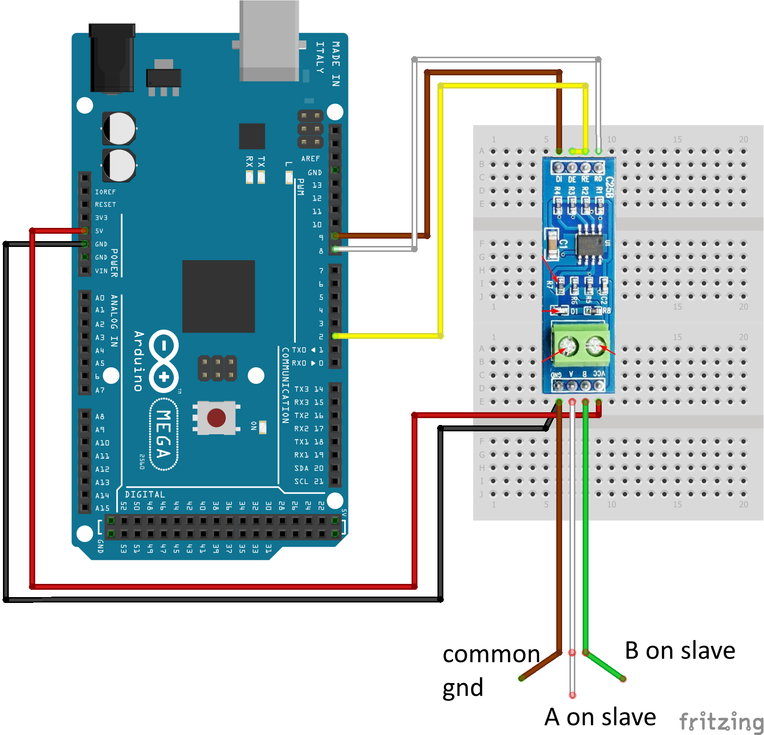
This is the exact wiring of how i have it set up right now.

As you can see i have a little piece of code that show what error is making node.ku8MBSuccess Fail.
this is the output i am getting from the serial monitor.

Screenshot 2023-10-18 092546

I really hope i have provided enough information. if someone has any clue of what is going on here don't hesitate to respond to this thread :slight_smile:

Well a little update to myself, i have hooked up the Arduino to an arduino slave program. I seem to get a response from the arduino to the slave simulator with a correct request for a specific holding register. The slave program seems to correctly return the answer back to the arduino mega. however the arduino keeps on saying that there has been an error reading the holding register.

#include <ModbusMaster.h>
#include <SoftwareSerial.h>

SoftwareSerial modbusSerial(2, 3);  // RX, TX for SoftwareSerial

#define RS485TransmitPin 4  // Pin to control DE/RE on RS485 module

ModbusMaster node;

void setup() {
  modbusSerial.begin(19200);  // Set the baud rate of your RS485 module
  pinMode(RS485TransmitPin, OUTPUT);

  // Initialize the ModbusMaster library
  node.begin(5, modbusSerial);  // Set the slave ID and serial port

  Serial.begin(9600);  // Initialize the serial monitor
}

void loop() {
  // Switch to transmit mode
  digitalWrite(RS485TransmitPin, HIGH);
  delay(100);

  // Send a Modbus request to read a holding register (e.g., 7001)
  node.readHoldingRegisters(7001, 1);
 

  // Switch to receive mode
  digitalWrite(RS485TransmitPin, LOW);
  delay(20);

  // Read data
  uint16_t result;
  if (node.ku8MBSuccess == node.readHoldingRegisters(7001, 1)) {
    result = node.getResponseBuffer(0);
    Serial.println("Holding Register Value: " + String(result));
  } else {
    Serial.println("Error reading holding register");
  }

  delay(10000); // Add a delay for control or adjust as required
}

this is the code that is currently running on the arduino mega. i have changed the wiring to RX=2 , TX=3 and the switching pin =4.

here we can see that the arduino is correctly requesting the data from the register that i have enabled. and returning with a correct code.

now its time for me to see how i can make it that the code will correctly read and process this data.

if anyone has some good advice i'd still like to hear it!

It may or may not help, but whenever I see delay() and software serial in the same description I get queasy. Software serial has serious limitations because all serial functionality is being done... by software. Timing is everything in Serial, so when your code 'takes a nap' there'd better be nothing coming at you on Serial, because you're going to miss it, or bits of it. Missing one bit means a character is wrong, and you'll never sort it out.
I always suggest that, if you're going to do anything with Software Serial, you do one thing, and one thing only, until it's complete. I'm going to go look at your code now, and see if I can see why you're having problems, and what can be done about it, but you've waited long enough for any response at all, so I thought I'd post this much.

When you switch to receive mode, remove that delay(20); or, reduce it drastically. There's no reason to delay, your code should simply be listening at that point; I think you might be missing the first few characters of the response.

Oops. No, it's more subtle than that.

  digitalWrite(RS485TransmitPin, HIGH);
  delay(100);
// Send a Modbus request to read a holding register (e.g., 7001)
  node.readHoldingRegisters(7001, 1);
  // Switch to receive mode
  digitalWrite(RS485TransmitPin, LOW);
  delay(20);

Presume your instrument is sitting there idle. You set the bus direction, napped for 100 mS, sent a request, immediately reversed bus direction (before the command was sent, I think, unless the read holding register code is blocking until serial transmit is complete, which would be unusual), then nap for 20 mS.
I don't see how that would work, but I avoid SSerial like the plague. I think you'd want to ensure the entire request has been sent before turning the bus around. Try moving the delay(20) to before the digital write, see if that helps.
Sorry, someone with more SSerial experience can probably help you better.

@camsysca thank you so much for taking the time to look at my code, the reason i used softserial is because in alll the other threads around here people say to absolutely avoid using the hardware serial. today i will be receiving a different type of MAX485 converter that switches automatically, so no more hassle with DE and RE pins. i think the DE and RE pins are what is mostly causing the troubles here as the timing is something that easily could go wrong. i will keep you updated. but already a huge thanks!

WHAT! That's complete garbage. I would always go for hardware serial over a software implementation.

EDIT: The avoidance of the hardware UART probably refers to using an UNO. You have a MEGA with 4 hardware UARTs.

In the code of your first post, your code says pin 3 controls RE & DE but your diagram shows pin 2 is used.

The modbusmaster library includes 2 callback functions just so that you can switch RE and DE at the correct time without using any delays.

void preTransmission()
{
  digitalWrite(MAX485_RE_NEG, 1);
  digitalWrite(MAX485_DE, 1);
}
void postTransmission()
{
  digitalWrite(MAX485_RE_NEG, 0);
  digitalWrite(MAX485_DE, 0);
}

And at the end of setup() you add:

node.preTransmission(preTransmission);
node.postTransmission(postTransmission);

thanks for your reply mark!
i will try again but with the hardware serial this time!
maybe that will be the golden solution. and you're right about the wiring scheme i see now haha, but i can assure you i wired it up correctly. let me try the hardware serial and i will let you know!

Also just noticed the document snippet says the default address is 12h which is 18, not 17.

that is also correct, however i have confirmed in the software for the slave device that the correct slave address is 17, you're very sharp so that is good haha.
Slave modbus settings

@markd833 i have altered the code now that it just uses the hardware serial pins on the Mega 2560. the code is working as before with my slave simulator receiving the correct request and returning data to the arduino. however ku8MBSucces still comes up as unsuccesfull giving me an error.

#include <ModbusMaster.h>

#define MAX485_RE_NEG 4  // Pin to control RE on RS485 module
#define MAX485_DE 3      // Pin to control RE on RS485 module

ModbusMaster node;

void preTransmission()
{
  digitalWrite(MAX485_RE_NEG, 1);
  digitalWrite(MAX485_DE, 1);
}
void postTransmission()
{
  digitalWrite(MAX485_RE_NEG, 0);
  digitalWrite(MAX485_DE, 0);
}

void setup() {

  Serial.begin(19200);  // Initialize the serial monitor


pinMode(MAX485_RE_NEG, OUTPUT);
pinMode(MAX485_DE, OUTPUT);

  // Initialize the ModbusMaster library
node.begin(5, Serial);  // Set the slave ID and serial port

node.preTransmission(preTransmission);
node.postTransmission(postTransmission);
}

void loop() {
  // Read data
  uint16_t result;
  if (node.ku8MBSuccess == node.readHoldingRegisters(7001, 1)) {
    result = node.getResponseBuffer(0);
    Serial.println(result);
  } else {
    Serial.println("Error reading holding register");
  }

  delay(10000); // Add a delay for control or adjust as required
}

DI = Tx0, Ro = Rx0, Re = pin4, De = pin 3. i have checked the wiring.

Use Serial1 for your RS485 Comms.

1 Like

ah yes good one, the gibberisch is gone now, but sadly still no luck on the reading part of the data. the arduino does not seem to be sending the request no to the slave sim. maybe my code is a bit off, still early today hahha.

#include <ModbusMaster.h>

#define MAX485_RE_NEG 4  // Pin to control RE on RS485 module
#define MAX485_DE 3      // Pin to control RE on RS485 module

ModbusMaster node;

void preTransmission()
{
  digitalWrite(MAX485_RE_NEG, 1);
  digitalWrite(MAX485_DE, 1);
}
void postTransmission()
{
  digitalWrite(MAX485_RE_NEG, 0);
  digitalWrite(MAX485_DE, 0);
}

void setup() {

  Serial.begin(19200);  // Initialize the serial monitor
  Serial1.begin(19200);


pinMode(MAX485_RE_NEG, OUTPUT);
pinMode(MAX485_DE, OUTPUT);

  // Initialize the ModbusMaster library
node.begin(5, Serial1);  // Set the slave ID and serial port

node.preTransmission(preTransmission);
node.postTransmission(postTransmission);
}

void loop() {
  // Read data
  uint16_t result;
  if (node.ku8MBSuccess == node.readHoldingRegisters(7001, 1)) {
    result = node.getResponseBuffer(0);
    Serial.println(result);
  } else {
    Serial.println("Error reading holding register");
  }

  delay(10000); // Add a delay for control or adjust as required
}

If you are using a PC program, then I assume you have an RS485 card or USB dongle. The PC program will show you the raw modbus message.

You can also use a serial terminal program on your PC to listen in and display the raw modbus message your MEGA is generating.

That way you can compare the 2 messages to see if there's a difference.

i will give that a try! a lot of these things are new to me so it might take a minute haha. thanks for your advice! ill get back to you when i have an answer :slight_smile:

i think i got it. as we can see weve got a serial coming in and a serial going out from the RS485 converter. the serial coming in is identical to the value i see in the modbus slave simulator which is the request. the value going out is identical to the one being sent back to the arduino from the slave simulator.

@markd833 It works!!

my dumb head didnt realise i need to switch the Real life serial port connection to serial1 aswell DUUHH. now i switched to RX1 and TX1 and boom it has a connection!

thank you so much for you help!

This topic was automatically closed 180 days after the last reply. New replies are no longer allowed.