Incremental rotary encoder and stepper motor help

I am very new to the Arduino world having great fun working it all out but struggling with some code issues

The project is, I wanted to is remove change gears from a metal lathe and replace it with a rotary encoder on the spindle, and put a stepper motor on the lead screw. then have the stepper motor turning at a specific speed in relation to the encoder spinning for example a 12 to 5 ratio

The products I have are a
incremental rotary encoder 600 pulses per rotation
Nema34 a stepper motor Single Shaft 8.7Nm1232oz
Micro stepper driver DQ860MA (So get 1600 steps per rotation on the moter)
Arduino uno

I have been able to find code and adapted so I can count the pulses (transitions) coming out of the encoder which gets 2400 per rotation of the encoder

But what I'm struggling with is linking that into the stepper motor the pins I'm using from the stepper driver to the Arduino are

PUL+(5v) PIN 8
PUL-(PUL) PIN 9
DIR+(+5v) PIN 10
DIR-(DIR) PIN 11

Rotary encoder pins
Channel A pin 2
Channel B pin 3

I don't know the right way of doing this but what I'm after is for every rotation of the encoder (2400 pulses). I want the stepper to rotate 0.8 of a turn constantly but as the encoder speeds Increases the stepper needs to speed be increased as well but I am unsure how to do this

I would very much appreciate if someone can play around with some code and explain what I'm after

Thank you very much for anyone who can help

Jim
Hi,
Welcome to the forum.

Please read the first post in any forum entitled how to use this forum.
http://forum.arduino.cc/index.php/topic,148850.0.html

Before you worry about connecting the two together you need to write your code in stages.

You have code that reads the encoder, which is good.
Now you need to write code that ONLY drives your stepper, no encode code at all in it.
Get the stepper code working, and understand how it works before attempting the combination of the two.

I hope your stepper is strong enough to do the job, because if it skips a step due to too high a physical load then you will be in trouble.
Electronic gearboxes sound simple, but in real life they can be very hard to implement.

You may need feedback from the stepper shaft to make sure it is moving the correct amount.

Can you post the code you have and a circuit diagram for the encoder part.

You need to look for an Arduino Library called AccelStepper, it also has example code for you to start programming for your stepper.

Tom.. :slight_smile:

hi tom

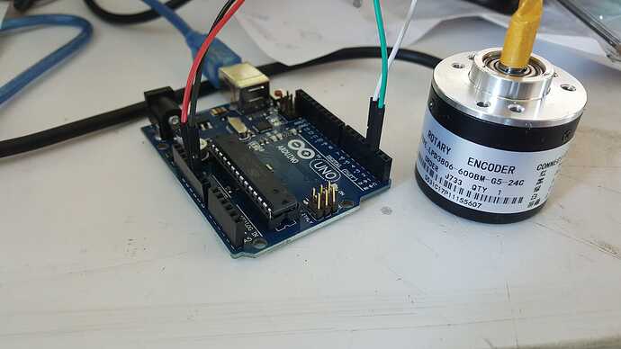
i have Attached a picture of the encoder wired into the Arduino the green wire is channel a and the white wire is channel b

Here is the code I have found for the encoder to count the pulses

//these pins can not be changed 2/3 are special pins
int encoderPin1 = 2;
int encoderPin2 = 3;

volatile int lastEncoded = 0;
volatile long encoderValue = 0;

long lastencoderValue = 0;

int lastMSB = 0;
int lastLSB = 0;

void setup() {
Serial.begin (9600);

pinMode(encoderPin1, INPUT);
pinMode(encoderPin2, INPUT);

digitalWrite(encoderPin1, HIGH); //turn pullup resistor on
digitalWrite(encoderPin2, HIGH); //turn pullup resistor on

//call updateEncoder() when any high/low changed seen
//on interrupt 0 (pin 2), or interrupt 1 (pin 3)
attachInterrupt(0, updateEncoder, CHANGE);
attachInterrupt(1, updateEncoder, CHANGE);

}

void loop(){
//Do stuff here

Serial.println(encoderValue);
delay(1000); //just here to slow down the output, and show it will work even during a delay
}

void updateEncoder(){
int MSB = digitalRead(encoderPin1); //MSB = most significant bit
int LSB = digitalRead(encoderPin2); //LSB = least significant bit

int encoded = (MSB << 1) |LSB; //converting the 2 pin value to single number
int sum = (lastEncoded << 2) | encoded; //adding it to the previous encoded value

if(sum == 0b1101 || sum == 0b0100 || sum == 0b0010 || sum == 0b1011) encoderValue ++;
if(sum == 0b1110 || sum == 0b0111 || sum == 0b0001 || sum == 0b1000) encoderValue --;

lastEncoded = encoded; //store this value for next time
}

I have managed to use that library with the examples in the software to make the stepper move and change speed, direction and steps

but I don't understand if the pulses from the encoder control the steps or the speed of the stepper

Thanks for your expertise

Hi,
Please read the first post in any forum entitled how to use this forum.
http://forum.arduino.cc/index.php/topic,148850.0.html then look down to item #7 about how to post your code.
It will be formatted in a scrolling window that makes it easier to read.

OPs Picture.

Tom... :o

jimlathe:
PUL+(5v) PIN 8
PUL-(PUL) PIN 9
DIR+(+5v) PIN 10
DIR-(DIR) PIN 11

Almost certainly the PUL- and DIR- just need to be connected to the Arduino GND.

You need to identify the number of steps the motor needs to make for every encoder step. Then it should be straightforward to relate the two.

To make it easier for people to help you please modify your post and use the code button </> so your code looks like this and is easy to copy to a text editor. See How to use the Forum

These links may be of interest
Stepper Motor Basics
Simple Stepper Code

You have not said what you want the powered lead-screw for. If you want to cut threads with it you will need to control the position of the lead-screw relative to the work piece as well as its speed.

...R