@surbyte eres un crack!! Muchas gracias por la aportación. Y siento no poder contestar antes
Sobre el punto 1, realmente són 5 i 7 segundos, aunque nose porué me hace ponerlo de esta forma (500000 i 700000) en vez de 5000 i 7000. En todo caso són delay demasiado altos, los he bajado a un segundo.
Sobre el punto 2, muchas gracias, realmente puedo ahorrarme el calculo repetitivo y hacer-lo como me dijiste.
Y sobre el punto 3, no havia caído en que realmente puedo hacerlo por pulsadores, ya que la lectura analógica constante crea esta demora que empeora la señal de salida. Lo he probado usando el led de la placa como en la fase anterior para configurar el DDS. Creeis que es la mejor forma? Realmente cuando coge bien el valor, la señal tiene mucha más calidad que antes, el problema es que a la que varia la lectura analógica a éste le cuesta procesar-lo. No se si es culpa de los delay() o de cuando el pin Led esta apagado. Es decir cuando mejor funciona es cuando coje un valor fijo en la lectura analógica.
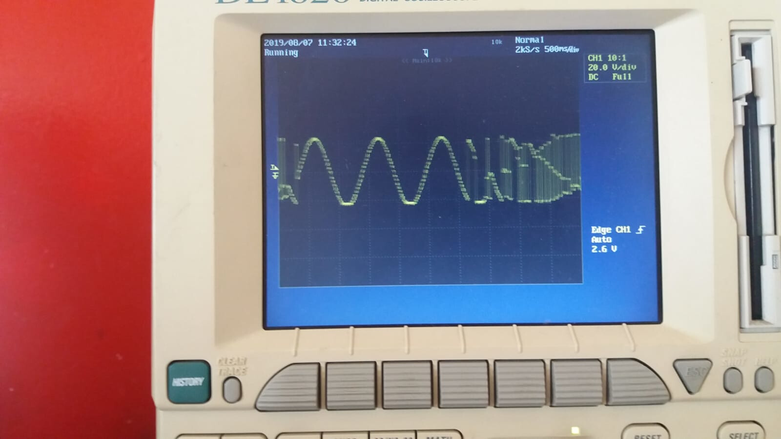
Les adjunto mi código y un par de fotos de la salida en el osciloscopio.
Muchisimas gracias comunidad arduino!!
#include <Wire.h>
#include <Adafruit_MCP4725.h>
#include "avr/pgmspace.h"
#include <avr/interrupt.h>
#include <avr/io.h>

#define cbi(sfr, bit) (_SFR_BYTE(sfr) &= ~_BV(bit))
#define sbi(sfr, bit) (_SFR_BYTE(sfr) |= _BV(bit))


Adafruit_MCP4725 dac;

int sineVal = 0;
int tono[ ] = {261, 277, 294, 311, 330, 349, 370, 392, 415, 440,466};
                   // mid C C# D D# E F F# G G# A
int p = 0;
int n = 0;
int ref1 = 0;
int ref2 = 0;
int ledPin = 13;


// table of 256 sine values / one sine period / stored in flash memory
const PROGMEM byte  sine256[]  = {
 127,130,133,136,139,143,146,149,152,155,158,161,164,167,170,173,176,178,181,184,187,190,192,195,198,200,203,205,208,210,212,215,217,219,221,223,225,227,229,231,233,234,236,238,239,240,
 242,243,244,245,247,248,249,249,250,251,252,252,253,253,253,254,254,254,254,254,254,254,253,253,253,252,252,251,250,249,249,248,247,245,244,243,242,240,239,238,236,234,233,231,229,227,225,223,
 221,219,217,215,212,210,208,205,203,200,198,195,192,190,187,184,181,178,176,173,170,167,164,161,158,155,152,149,146,143,139,136,133,130,127,124,121,118,115,111,108,105,102,99,96,93,90,87,84,81,78,
 76,73,70,67,64,62,59,56,54,51,49,46,44,42,39,37,35,33,31,29,27,25,23,21,20,18,16,15,14,12,11,10,9,7,6,5,5,4,3,2,2,1,1,1,0,0,0,0,0,0,0,1,1,1,2,2,3,4,5,5,6,7,9,10,11,12,14,15,16,18,20,21,23,25,27,29,31,
 33,35,37,39,42,44,46,49,51,54,56,59,62,64,67,70,73,76,78,81,84,87,90,93,96,99,102,105,108,111,115,118,121,124

};


double dfreq;
// const double refclk=31372.549;  // =16MHz / 510
const double refclk=31376.6;      // measured

// variables used inside interrupt service declared as voilatile
volatile byte icnt;              // var inside interrupt


volatile unsigned long phaccu;   // pahse accumulator
volatile unsigned long tword_m;  // dds tuning word m
volatile int timerTick = 0;

void setup(void) {

  pinMode(ledPin, OUTPUT);
  Serial.begin(9600);

     // For Adafruit MCP4725A1 the address is 0x62 (default) or 0x63 (ADDR pin tied to VCC)
  // For MCP4725A0 the address is 0x60 or 0x61
  // For MCP4725A2 the address is 0x64 or 0x65

  dac.begin(0x60);


 Setup_timer2();

 // disable interrupts to avoid timing distortion
    cbi (TIMSK0,TOIE0);              // disable Timer0 !!! delay() is now not available
    sbi (TIMSK2,TOIE2);              // enable Timer2 Interrupt

}


void loop(void)
{
      while ((ref1 == 0) and (ref2 == 0))
      {

        digitalWrite(ledPin, HIGH);   // turn the LED on (HIGH is the voltage level)
          ref1 = analogRead(A0);
          Serial.print (ref1);
        delay(100000);                       // wait for a second

        digitalWrite(ledPin, LOW);    // turn the LED off by making the voltage LOW
        delay(100000);

        digitalWrite(ledPin, HIGH);
          ref2 = analogRead(A0)+ 20;
          Serial.print (ref2);
        delay(100000);
       }


        digitalWrite(ledPin, HIGH);   // turn the LED on (HIGH is the voltage level)

          p = analogRead(A0);
          n = map (p, ref1, ref2, 0, 11) ; // Ell array solo tiene 12 notas
          double ValorFr= tono[n]*0.4;

          dfreq=ValorFr;                    // initial output frequency = 1000.o Hz
          tword_m=(136884*dfreq);  // calulate DDS new tuning word

         delay (1000);

        digitalWrite(ledPin, LOW);    // turn the LED off by making the voltage LOW

         tword_m=(136884*dfreq);  // calulate DDS new tuning word


        delay(1000);


if (timerTick = 1)
     {


 dac.setVoltage(sineVal, false);

 timerTick = 0;
     }


}


//******************************************************************
// Timer2 Interrupt Service at 31372,550 KHz = 32uSec
// this is the timebase REFCLOCK for the DDS generator
// FOUT = (M (REFCLK)) / (2 exp 32)
// runtime : 8 microseconds ( inclusive push and pop)
// 125 ticks = 4 milliseconds
ISR(TIMER2_OVF_vect)
 {


  phaccu=phaccu+tword_m; // soft DDS, phase accu with 32 bits
icnt=phaccu >> 24;     // use upper 8 bits for phase accu as frequency information

  sineVal = (pgm_read_byte_near(sine256 + icnt))<<4;


     timerTick = 1;


 }

//******************************************************************
// timer2 setup
// set prscaler to 1, PWM mode to phase correct PWM,  16000000/510 = 31372.55 Hz clock
void Setup_timer2() {

// Timer1 Clock Prescaler to : 1
 sbi (TCCR2B, CS20);
cbi (TCCR2B, CS21);
 cbi (TCCR2B, CS22);

 // Timer1 PWM Mode set to Phase Correct PWM
cbi (TCCR2A, COM2A0);  // clear Compare Match
 cbi (TCCR2A, COM2A1);

 cbi (TCCR2A, WGM20);  // Mode 1  / Phase Correct PWM
 cbi (TCCR2A, WGM21);
 cbi (TCCR2B, WGM22);
}
/**************************************************************************/

/**************************************************************************/