I've a circuit (shown below) with an input which is normally high (5v). I want to light an indicator LED when the input goes low so I stuck in an LED and resistor connected between Vcc and the input and thought I was awfully clever.
The problem I have is, with my selected components, the voltage level on the GPIO pin sits about 1.1V when the input goes low. I've limited information about the board the GPIO is on so I don't know what it's capable of sinking, the logic threshold for LOW, etc.
I can obviously 'fix' this by increasing the resistor value and that works but I'd like to put a more robust solution in place.
I'm guessing a transistor is the way to go and I'm off to investigate that now but I thought I'd check how other people handle this requirement and if there's a better way?
So the problem is the input pin not going low enough. No so much LED current.
Use a small-signal PNP transistor.
Collector to ground, emitter to LED cathode, base to GPIO pin. No resistors.
Cathode voltage will be ~0.7volt when low, so calculate LED resistor accordingly.
GPIO pin is now only influenced by base current of the transistor, wich is significantly lower than the LED current.
Leo..
What is driving that input? Probably not a switch is it? Whatever is driving the input needs to be able to sink the current of the led. So increasing the resistor will decrease the current so probably decrease the voltage when low. (But of course also decrease the amount of light).
You could indeed use a transistor to fix it.
But why would you? 1,1V is a perfectly normal LOW for a 5V Arduino.
The input is being driven by an ADuM5241 DC/DC isolator (PDF Datasheet).
If I'm reading the datasheet right, table 7 on page 7 says it can only sink 18mA which doesn't seem like a lot. I hadn't checked that before.
The GPIO is on a Sensoray 2253 USB video capture card. The documentation is here (PDF) but doesn't give a lot of detail.
Use a small-signal PNP transistor.
Collector to ground, emitter to LED cathode, base to GPIO pin. No resistors.
Wawa, when you say 'no resistors' I assume you mean on the base and collector pins? The LED will still need a limiting resistor? You mention the taking the voltage on the emitter into account when selecting a limiting resistor so that seems clear enough, just checking.
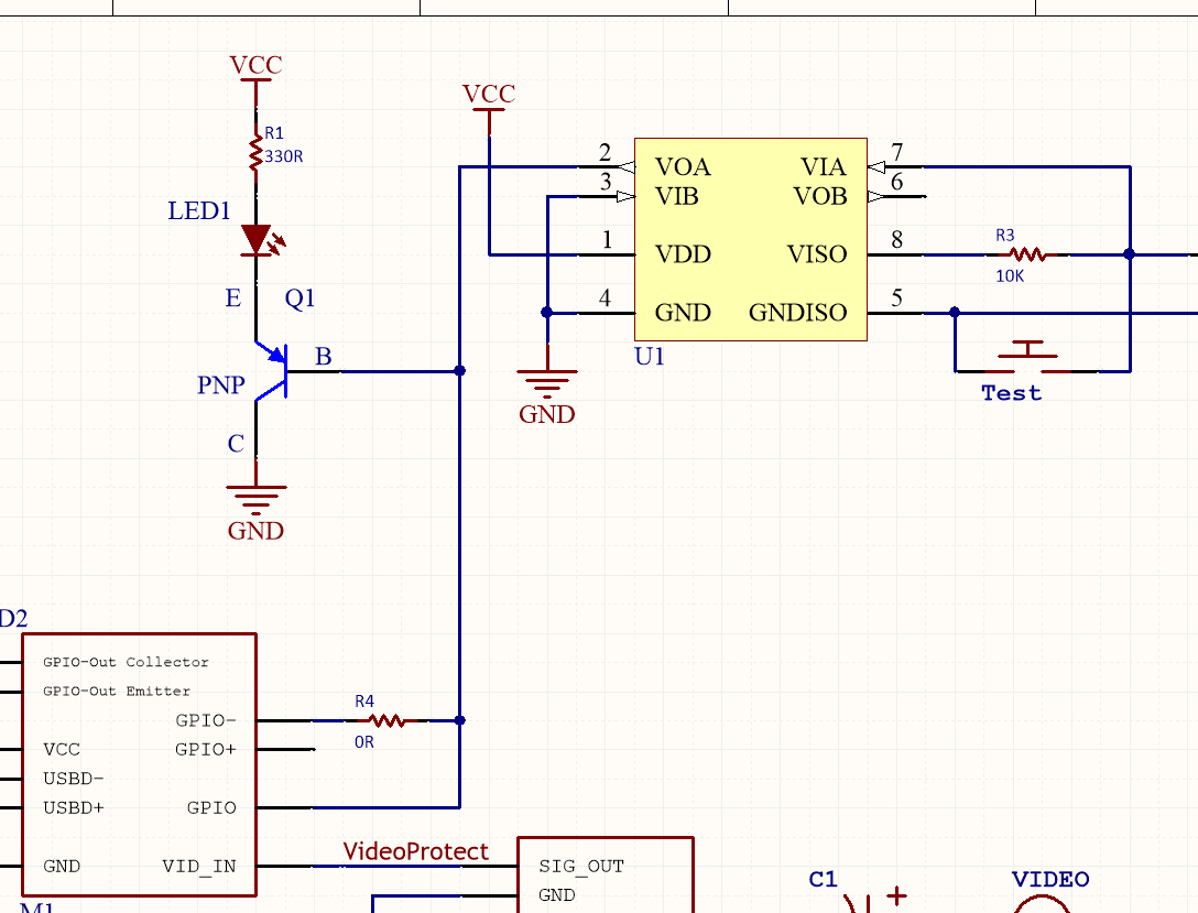
I've gone with this design, does it look OK? The transistor is the ON Semi MMBT4126LT3G PNP Bipolar Transistor, 0.2 A, 25 V, 3-Pin SOT-23 Datasheet via RS
Yes, only a LED current limiting resistor, no base resistor.
This is an emitter follower.
Base current is LED current divided by the DC gain of the transistor.
So base current (sink) is now about 25uA.
Leo..