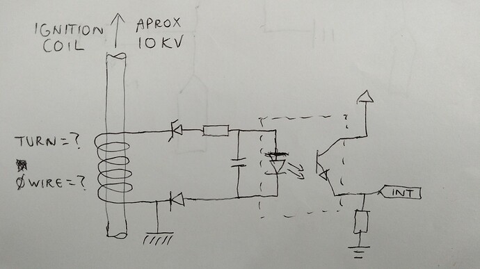
I want to make inductive tachometer on single cylinder engine with coil wire, is my sketch can be applied? Anyone have a formula to measuring the coil specs?
Is it a magneto ignition? Much easier to fix a tiny magnet to a shaft and use a Hall Effect pickup. There are sketches around for Arduino tachos and you can actually buy them ready-made on the 'bay.
If you can get access to the core of the coil, wind one turn round it and use a scope to look at the waveform which will tell you the voltage - if you need Nx more then wind N turns.. Why two diodes with the Schottky one facing the wrong way? Why the capacitor? If you are adding a coil why use an opto at all?
What is the name of the device on 3bay?
I mean it zener and cap for filtering
The zener is just stopping any pulses smaller than the zener voltage doing anything.
Hi,
Rather than wind the coil around the ignition lead where any leakage of the spark will cause some circuit damage.
Try using a toroidal core to pass the ignition lead through and winding the pick up coil on the toroid, this is how the professional test gear do it.
In fact they make clamp on accessories to clamp the lead, some how ever are quite expensive ( over priced ), so DIY is better.
Usually about 4 or 5 turns will do the trick, weather you have enough signal to fire the LED in the opto will need to be experimented with.
Forget the in series zener, put it across the resistor LED circuit.
Tom... ![]()
![]()
![]()
![]()
PS. 25years servicing automotive test equipment.
I'll try it later
This topic was automatically closed 180 days after the last reply. New replies are no longer allowed.

