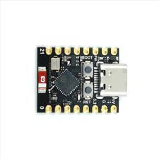
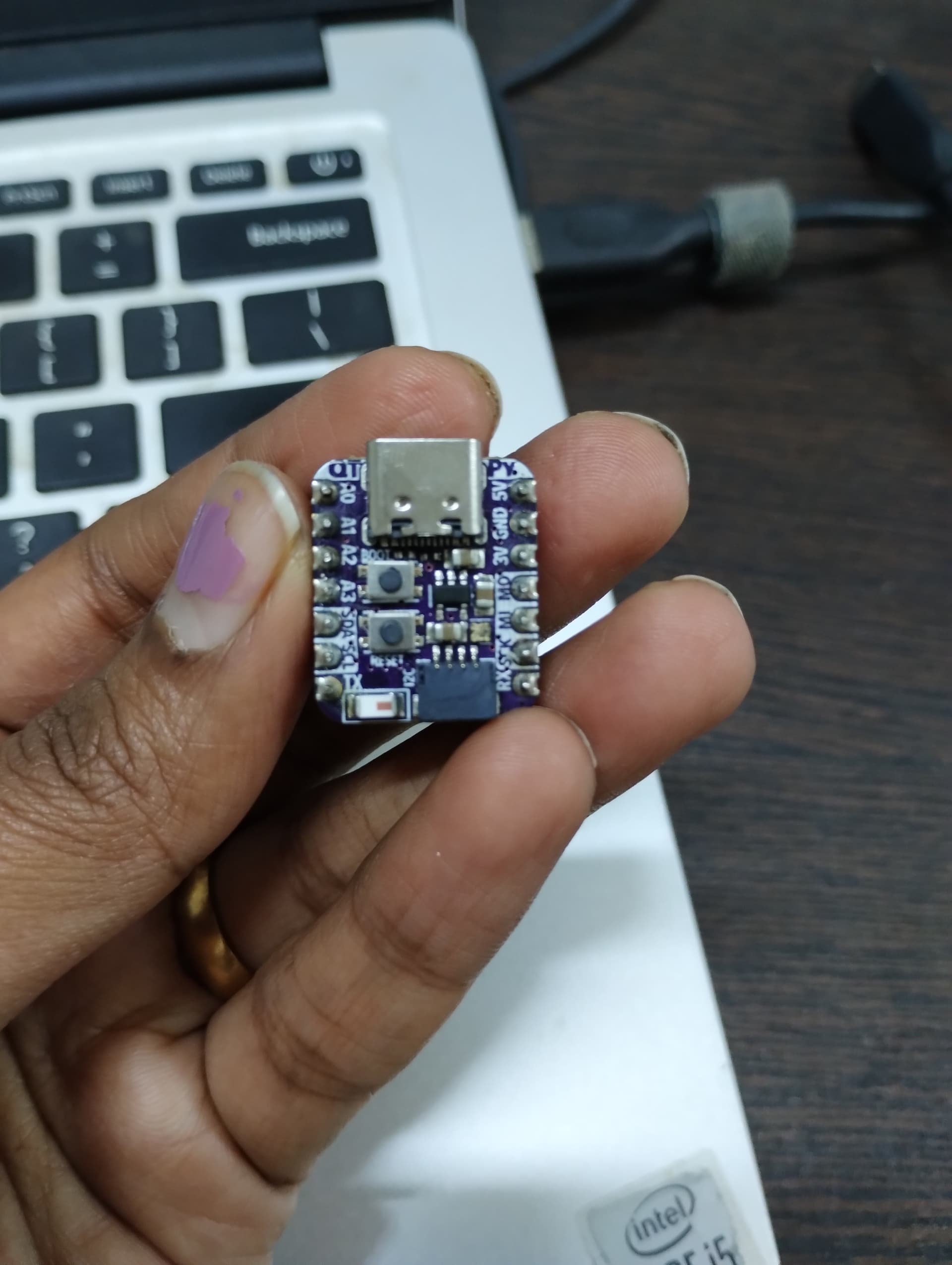
I have interfaced MAX30001 which a SPI sensor with arduino UNO and ardduino R4 minima. The arduino code is working as expected. But when used with adafruit QT PY ESP32-C3, the sensor is not initializing. So I tried using the HSPI class but that is also not working
#include <SPI.h>
#include "max30001.h"

#define HSPI_MISO 8
#define HSPI_MOSI 7
#define HSPI_SCLK 10
#define HSPI_CS   20
#define MAX30001_SPI_SPEED 1000000

SPIClass * hspi = NULL;

MAX30001 max30001(HSPI_CS);

void setup()
{
  Serial.begin(9600);

  SPI.begin(HSPI_SCLK, HSPI_MISO, HSPI_MOSI, HSPI_CS);

  /*hspi = new SPIClass(HSPI);
  hspi->begin(HSPI_SCLK, HSPI_MISO, HSPI_MOSI, HSPI_CS); //SCLK, MISO, MOSI, SS
  pinMode(HSPI_CS, OUTPUT); //HSPI SS*/

  bool ret = max30001.max30001ReadInfo();
  if (ret)
  {
    Serial.println("MAX 30001 read ID Success");
  }
  else
  {
    while (!ret)
    {
      // stay here untill the issue is fixed.
      ret = max30001.max30001ReadInfo();
      Serial.println("Failed to read ID, please make sure all the pins are connected");
      delay(5000);
    }
  }

  Serial.println("Initialising the chip ...");
}

void loop()
{
}

void max30001RegWrite(unsigned char WRITE_ADDRESS, unsigned long data)
{
    // Combine the register address and the command into one byte:
    byte dataToSend = (WRITE_ADDRESS << 1) | WREG;

    SPI.beginTransaction(SPISettings(MAX30001_SPI_SPEED, MSBFIRST, SPI_MODE0));

    digitalWrite(HSPI_CS   , LOW);

    delay(2);
    SPI.transfer(dataToSend);
    SPI.transfer(data >> 16);
    SPI.transfer(data >> 8);
    SPI.transfer(data);
    delay(2);

    digitalWrite(HSPI_CS   , HIGH);

    SPI.endTransaction();
}

void max30001RegRead(uint8_t Reg_address, uint8_t *buff)
{
    uint8_t spiTxBuff;

    SPI.beginTransaction(SPISettings(MAX30001_SPI_SPEED, MSBFIRST, SPI_MODE0));

    digitalWrite(_cs_pin, LOW);

    spiTxBuff = (Reg_address << 1) | RREG;
    SPI.transfer(spiTxBuff); // Send register location

    for (int i = 0; i < 3; i++)
    {
        buff[i] = SPI.transfer(0xff);
    }

    digitalWrite(_cs_pin, HIGH);

    SPI.endTransaction();
}

bool max30001ReadInfo(void)
{
    uint8_t readBuff[4];

    _max30001RegRead(INFO, readBuff);

    if ((readBuff[0] & 0xf0) == 0x50)
    {
        Serial.print("MAX30001 Detected. Rev ID:  ");
        Serial.println((readBuff[0] & 0xf0));

        return true;
    }
    else
    {

        Serial.println("MAX30001 read info error\n");
        return false;
    }

    return false;
}
try running esp32-spi-communication which prints the default SPI pins
on the ESP32-C3-MINI-1 and ESP32-C3 supermini using Tools>Board ESP32C3 Dev Module it displays
MOSI: 6
MISO: 5
SCK: 4
SS: 7
when interfacing a 1_8_inch_ST7735_TFT display I used the default MOSI, MISO, and SCK pins and also defined
just noted you are using GPIO20 which on the ESP32C3 GPIO20 is U0RXD which with GPIO21 U0TXD are used for Serial programming/debugging
if you are using Serial IO doubt if you can also use it for HSPI_CS
you can remap the SPI pins but ESP32C3 GPIO20 is U0RXD is already used for Serial RX so I doubt if you can use it for CS - you can try! why not just use the default pin 6?
I am using only SPI..Correct me if I am wrong, for Serial printing U0RXD is needed. I am trying to mount the sensor on the QT PY, for this purpose CS pin needs to 20.