Hello,
i have newly purchased one module of RS232 (MAX232/TTL) and have tried to interface it with the ESP32S-DevKitc-1 i have.
Reading from the ESP32S and printing it one the Serial Monitor is working very well.
The problem is when i try to write anything from the Serial Monitor to the ESP32S3, then it's not working.
THe connections are like follow:
ESP32 RXD -> MAX232 RX
ESP32 TXD -> MAX232 TX
My module works with 3V3.
I am using the example from the Arduino IDE (e.g. Examples -> communications -> Multiserial)
I am using pins:
GPIO18 -> RXD
GPIO17 -> TXD
The Mudole which i use:

I would appreciate any suggestions.
Thanks in Advance.
Swap these 2 connections.
Are you sure? I may be wrong here, but the MAX232 chip is designed for 5V systems. It may not generate the RS232 voltage levels correctly when powered from 3.3V.
1. Can you communicate between the Serial Monitor and ESP32 using the following setup (Fig-1)?

Figure-:1
2. Now, do you want to communicate with a second Serial Monitor using the following setup (Fig-2)? You need to use level shifter as ESP32 is a 3.3V device and MAX232 is a 5V device. You also need RS232/USB adater cable to connect MAX232 with PC.
Figure-2:
According to Amazon (where i get this module) it's compatible with 3v3 to 5v.
I have already swapped this tow pins. No chance
@GolamMostafa
According to setup (Fig-1) i can communicate.
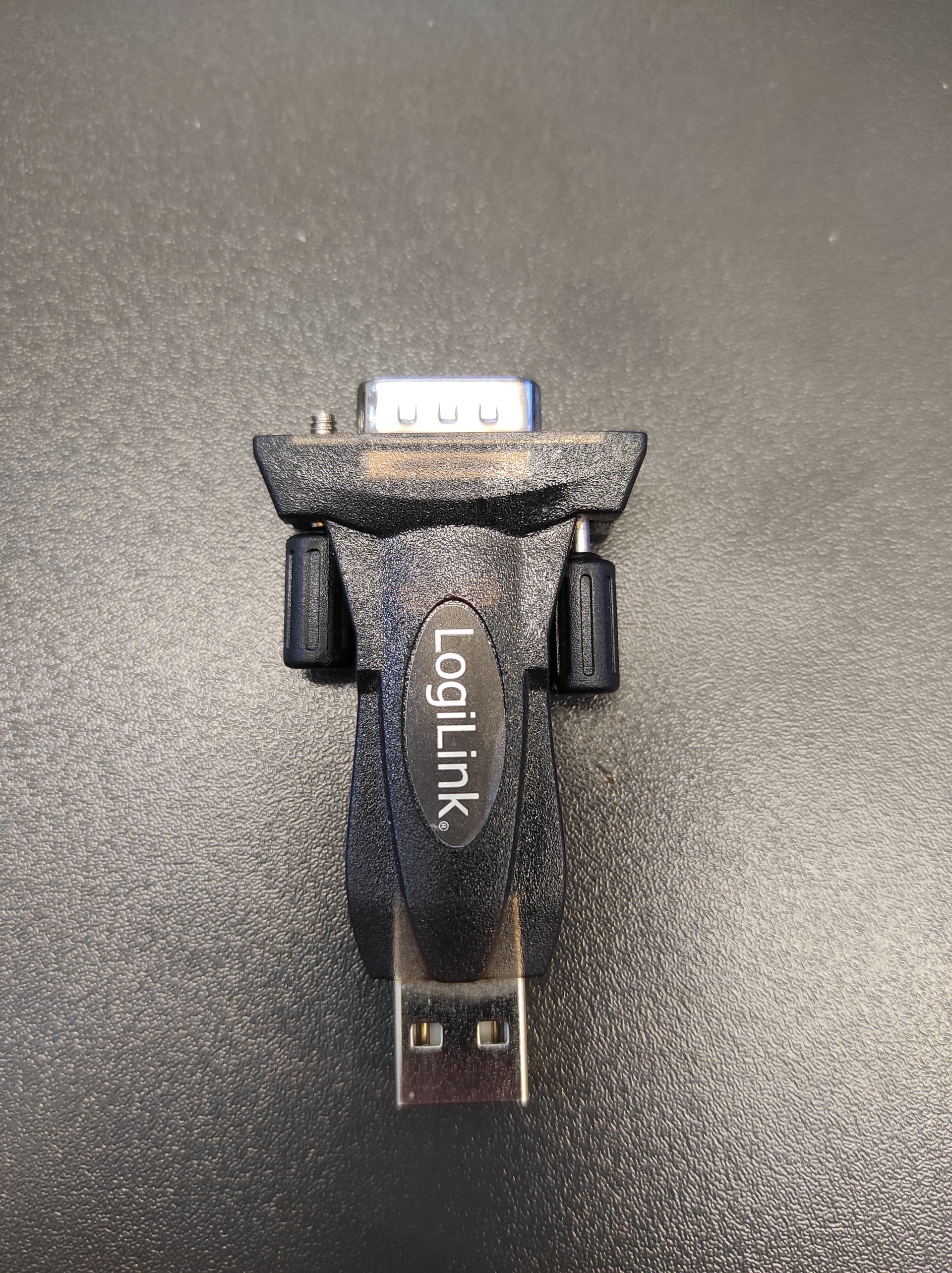
AS RS232 <- -> USB i am using Logilink RS232 to USB
Then use the following setup (Fig-1):
Figure-1:
Now. which setup you want to try -- Fig-2 of post #3 or Fig-1 of post #6
I have already tried Fig-1 of post #6.
The problem is only writing to the ESP32S3
Reading from ESP32S3 is already working.
I swapped the pis -> not working.
But i may purchase level shifter and then try the other setup
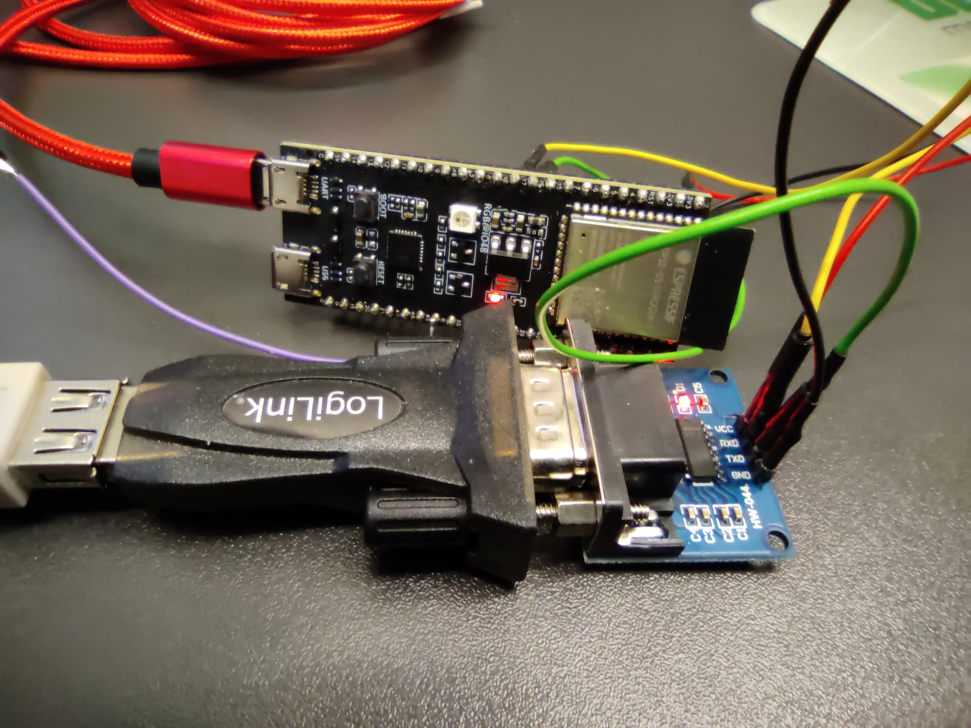
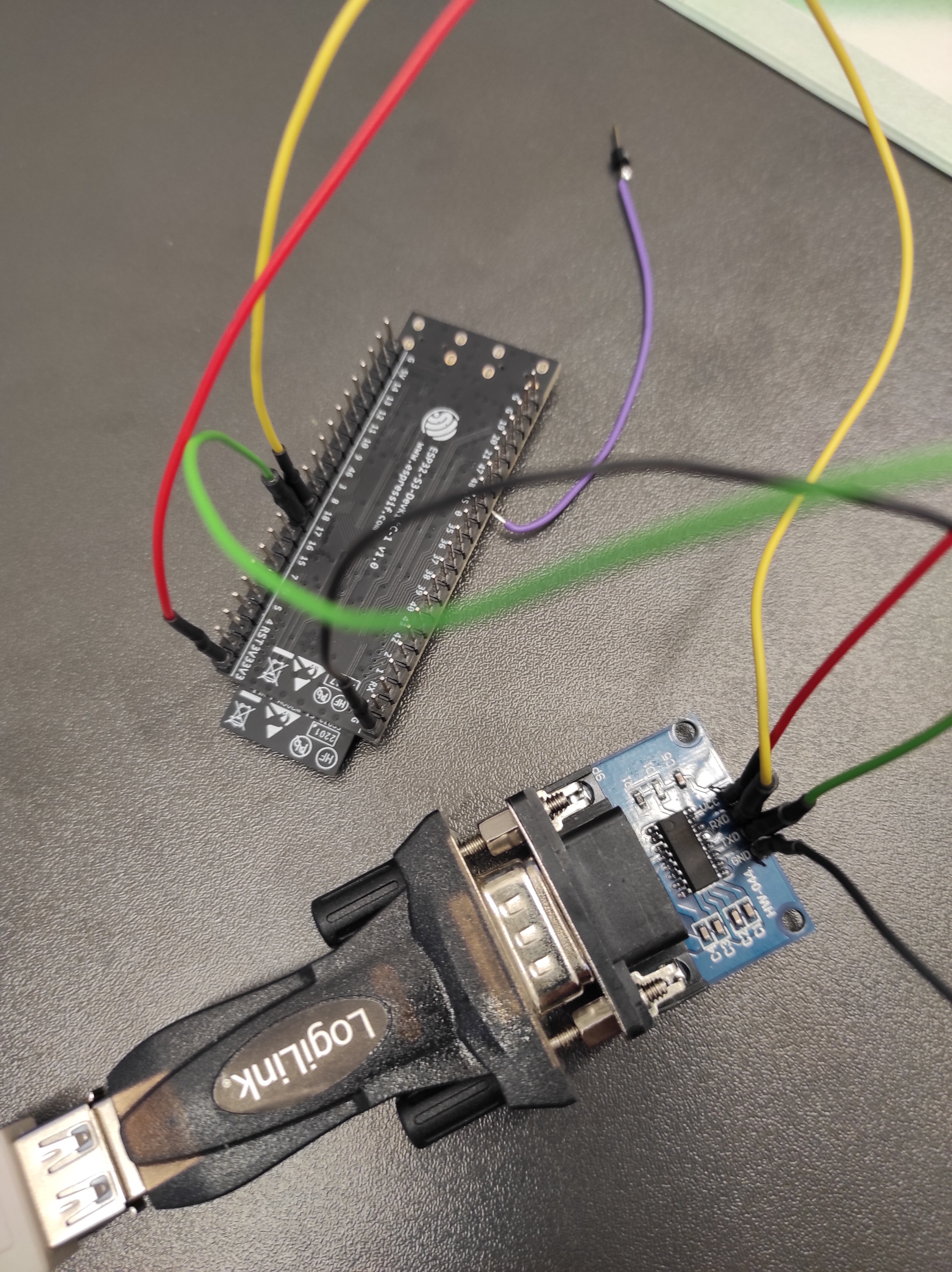
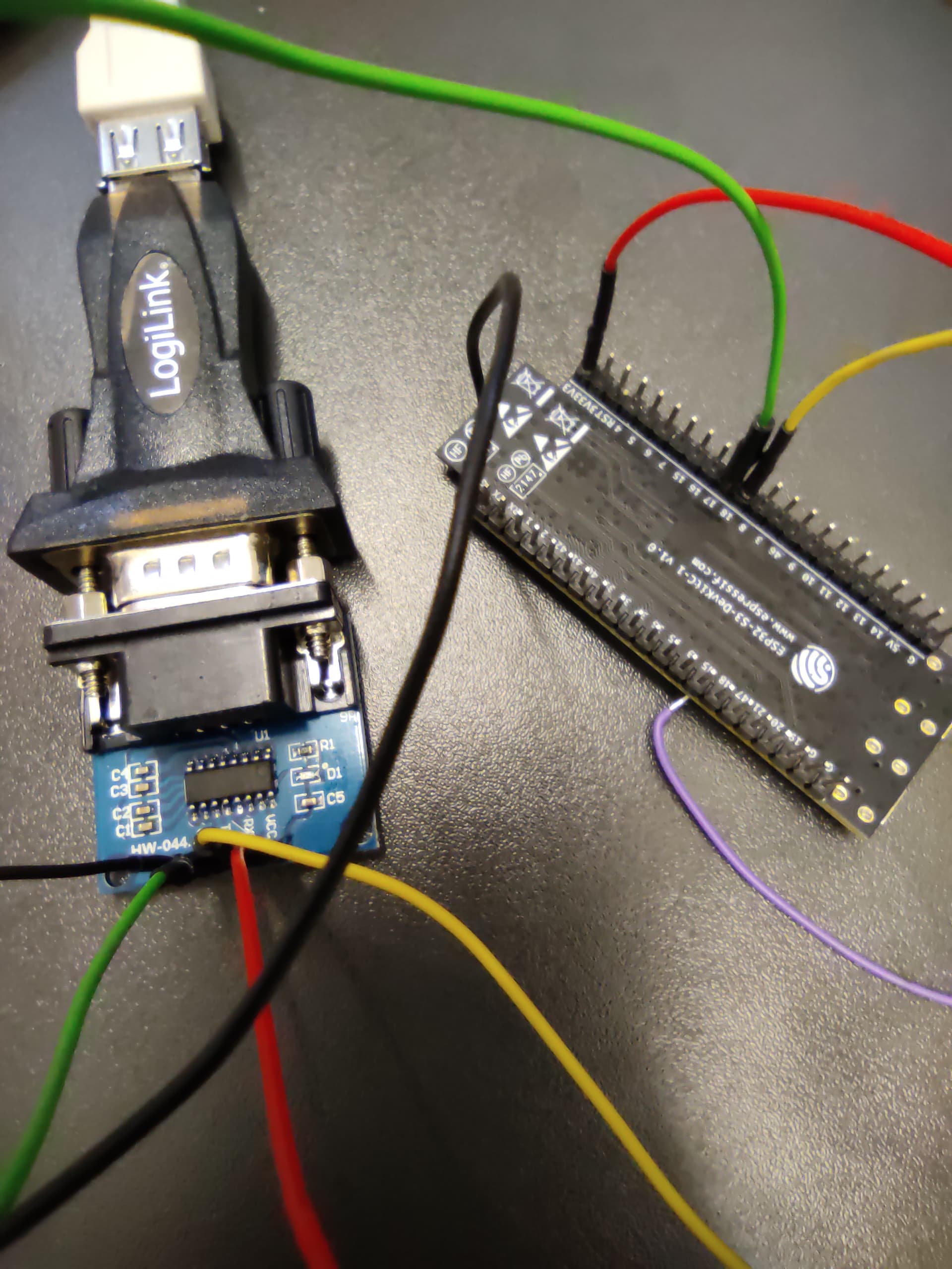
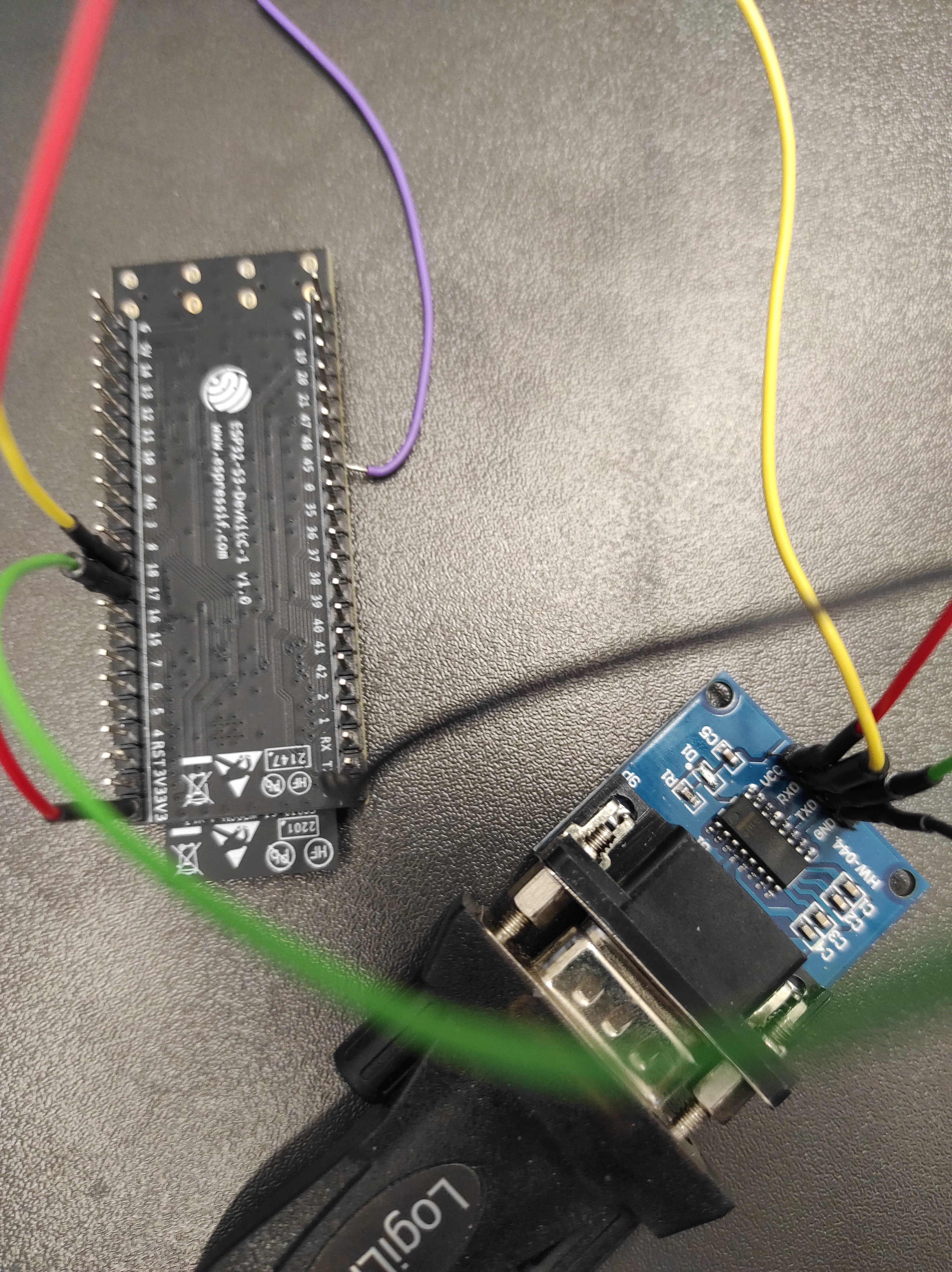
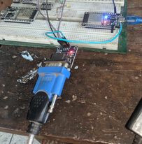
Which set up you have now on the working bench -- show the picture of the setup?
Can you please, make a shot of the setup and post here? Also, post the sketch/codes.
OK, i hope my shots are good enough
#define RXD 18
#define TXD 17


void setup() {
  // initialize both serial ports:
  Serial.begin(9600);
  Serial1.begin(9600, SERIAL_8N1, RXD, TXD);
}

void loop() {
  // read from port 1, send to port 0:
  if (Serial1.available()) {
    int inByte = Serial1.read();
    Serial.write(inByte);
  }

  // read from port 0, send to port 1:
  if (Serial.available()) {
    int inByte = Serial.read();
    Serial1.write(inByte);
  }
}
Good!
Try the following, which I have tested (Mine TTL/RS232 dapater is equipped with MAX2323 chip which works with both (3.3V and 5V):
1. Connect TTL/RS232 adapter with RS232/USB Cable.
2. Short TXD and RXD pin on TTL/RS232 Module.
3. Connect 3.3V and GND with TTL/RS232 Module.
4. Connect the cable wit USP Port of PC.
5. Goto Device Manager and record the COM Port.
6. Open IDE and select the COM Port of Step-5.
7. Open Serial Monitor at Bd = 9600.
**8. ** Eneter 1234 in the InputBox of Serial Moniotr wth Newline option and then click on the Send Button.
9. Check that 1234 hasa apperaed on the OutputBox of Serial Monitor.
10. This ends the functionlity check of adapters in loop back mode.
11. Next to connect ESP32.....
I did what you suggested from 1. to 8.
Is the send button (Enter)?
1234 hasn't appeared on the OutBox of Serial Monitor
Your adapter setup is faulty. Make it right first. Mine setup works well in loop back mode.
1. For me, the setup of Fig-1 of post #6 works (Fig-1).

Figure-1:
2. I have uploaded the following sketch (your sketch of post #13 with some modifications).
void setup()
{
  Serial.begin(9600);
  Serial2.begin(9600);
}

void loop()
{
   if (Serial.available())
   {
    char inByteSM1 = Serial.read();
    Serial2.print(inByteSM1); //sending to SM2
  }

  if (Serial2.available()) //get from SM2 via adater cables
  {
    char inByteSM2 = Serial2.read();
    Serial.print(inByteSM2);
  }
}
3. Procedures:
(1) Upload sketch of Step-2 into ESP32.
(2) Open Serial Monitor (SM1) at Bd = 9600 with Newline option.
(3) Open another new IDE.
(4) Select Arduino UNO Board; but, do not connect the board.
(5) Select the COM Port which should be different from ESP32's Port. If needed, check in the Device Manager.
(6) Open Serial Monitor (SM2) at Bd = 9600 with NEwline option.
(7) Excahne data between SM1 and SM2 enetering data in the respective InputBox.
With the same sketch, it works for me too.

Thank you for your help.
You mean the sketch of post #13 (yours)?