Could be a good move to get the valve wiring off the micro ground all together and give the micro it's own separate supply.
From what I can see there appears to be opto isolators to the relay board which are essentially useless the way things are.
You pay your money, you take your chances --
Are you saying to have a common running into the box as well? Right now the commons are connected outside the box.
The way I have it now is that one "line" comes into the box and is daisy chained through the relays.
As in to have a separate supply for the micro and one for the relay board?
The valve wiring has it's own supply other than that it shares the same outlet/breaker.
I don't follow what you're saying?
I guess it was a long time ago -
"Also, would adding a snubber or varistor on the load side of solenoid help with this issue?"
Here's 10 for $11 (shipped, wait a while
And "alice..." is a very good seller (IMHO).
I thought that is what you were referring to. Sounds like you're pro snubber or varistor.
Well, what's $11 ?
Yep. It's not so much the money either, got way too much time in this project!
Nothing ventured, nothing gained.
1 Like
MOV-14D470K .... datasheet
These are 30VAC RMS MOVs and should work well if connected at each relay that switches a solenoid (connect across COM and NO terminals).
Thanks for that! I will look into ordering these.
I'm outputting about 29.5VAC, and about 28VAC with one relay and 27VAC with two relays on. Is that cutting it close with these and step up one more size or you think they'll be fine?
Yeah, that's too close ... this MOV is 35VAC RMS ... MOV-14D560KTR
Fair enough as it started with your supplying one of those rats nest fritzing diagrams.
Why do you insist on raging on me about the fritzing diagram?
Keep in mind that not everyone is an electrical engineer (myself included).
The only skills I have in reading and writing electrical drawings are what I teach myself or learning from others online.
I have no prior electrical schooling.
I have no prior programming schooling.
I have made this project and others with self research and help from others on forums like this.
I appreciate your and others help, and yes I could have done better with up to date schematics but as I mentioned above, this is what I have to deal with without disassembling my box.
People learn from mistakes, and my mistake was not keeping up to date drawings (point taken).
The past is exactly that, the past.
Point being you expect "fix" answers from rubbish so called "diagram"
Which I did get the helpful suggestions I was hoping for.
I wasn't asking someone to dissect an electrical drawing, I was merely looking for suggestions on ways to help with an interference issue.
"Has that issue been resolved, so you can tell everyone how you resolved it, as is customary on this forum, and mark it [solved]?"
It has been working without issue for the last couple days so far with heavy usage.
Things done so far:
-Grounded metal plate installed between controller and relay board.
-Isolated some wires related to the controller away from 24VAC wiring (which I think may have been the bigger difference).
I am going to add a varistor or snubber in on the solenoid load yet, as suggested above. I will have to order some parts yet. As grumpy_mike had mentioned above "the more mitigation measures you use the more immune a system will become." So even though it has been working, I will do the above for sure yet.
I will also be doing some research on a pi filter yet, as I am unfamiliar with this.
1 Like
Last two circuits on this page
http://www.thebox.myzen.co.uk/Tutorial/De-coupling.html
The schematic looks like a Pi symbol hence the name.
Thanks! I will be checking into that yet too.
It has been working now without an issue since the metal plate and isolating of wires.
I haven't got around to ordering the other protective measure parts yet.
Here are some images of the app control for this.


When running...

Update:
I still was having slight occasional interference issues after the metal plate.
So I added a snubber in for each solenoid valve which seems to have solved the problem.
Been running heavy for 3 weeks with zero issues.
0.1 uF capacitor
47 ohm 1/2w carbon film resistor
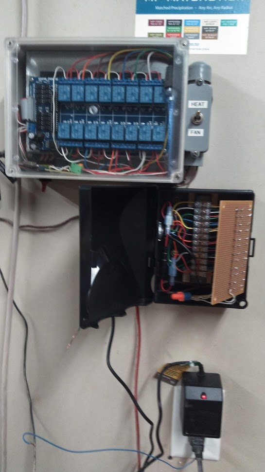
I added in the black box below to add the snubbers, which also tidied up my valve wiring connections.
Ended up putting a snubber for each valve and one for pump start relay, (snubber across the solenoids and pump relay).
Also added in a 800ma fuse in for the 24VAC.
Thanks for the advice and help!


1 Like
This topic was automatically closed 180 days after the last reply. New replies are no longer allowed.