I got my Micro second hand. All of the outputs work fine so now I hooked up some buttons between the pin and ground. According to the serial monitor, none of them trigger.
I checked the voltages at the pins. A pin with with INPUT_PULLUP set reads 1.9v at the pin, when I press the switch it drops to 1.7v. That isn't right, right? The pullup should be up to 5v? I checked every pin I could with input_pullup and they either read 1.9v or 0. I'm guessing something is wrong here?
Thanks.
2 things:
Can you blink an LED/resistor using the pin in question, by using the blink sketch and changing the pin number?
How is the switch wired?
I tested 5 pins. (5 and 13 read the 1.9v with the pull-up and 6,7,12 all read 0v with the pull-up as i mentioned in the first post.)
All 5 of them blink the led just fine.
The switches (on 5,6,7,12. I never had anything connected to 13 and used that just to test things) are connected from pin to switch to ground.
To answer your question, something is wrong here, yes it seems so. I have never heard of internal pull-up not working but the MCU otherwise working to do something like blink a pin. So it's probably time to scrutinize your wiring and sketch. Let's see a photo of your wiring with neatly routed wires and good light. A schematic. And your sketch enclosed in code tags, and what you see in the serial monitor. You may have something basic that is not quite right and another set of eyes on it may help.
dmjlambert:
...with neatly routed wires.
I can feel the shame and ridicule already...
Let me gather all that together and try to clean things up.
Thank you for your help so far. It gives me hope.
Yes, I can feel it too!  Make sure the wires are the right colors!
Here is the schematic, code, and pics of the buttons. I know how bad it all looks but all the buttons worked when tested with a bench power supply and the led lit up correctly before being hooked up to the micro.
void setup(){
Serial.begin(9600);
pinMode(5,INPUT_PULLUP);
pinMode(6,INPUT_PULLUP);
pinMode(7,INPUT_PULLUP);
pinMode(12,INPUT_PULLUP);
}

void loop(){
Serial.print("5: ");
Serial.println(digitalRead(5));
Serial.print("6: ");
Serial.println(digitalRead(6));
Serial.print("7: ");
Serial.println(digitalRead(7));
Serial.print("12: ");
Serial.println(digitalRead(12));
delay(20);
}
The serial output is
5: 1
6: 1
7: 1
12: 1
Pressing any of the 4 buttons does not change anything on the serial output.
The voltage on the 4 pins are all ~1.8v-1.9v.
Pressing the button on 5,6,7 drops it to ~1.7v
Pressing the button on 12 drops it to 0v.
I was playing around and added a manual pull-up just to see what would happen. I attached that schematic as well. The output here is more confusing so probably rigged up wrong haha.
Pins 6,7,12 read 0v. Serial output is 1 but pushing any of those 3 buttons will cause all three to go low. They also flutter to 0 every so often with nothing happening as well.
pin 5 reads 4v, when pushed goes to 2v but always reads high on the serial output ("5: 1")
A few things come to mind:
-
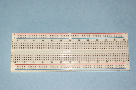
If you're using a breadboard and using the supply rail across the top or bottom, and it is the type that are not connected all the way across, that messes up some folks. Split power rails. You can tell if it's that kind of breadboard by the break in the blue and red stripes on the board.
-
I would leave the LEDs and resistors out of the circuit for now and just get it going with a simple switch, as in this tutorial: Gammon Forum : Electronics : Microprocessors : Switches tutorial
-
If you have those tactile buttons with the 4 legs, those get me confused all the time, and I have to get out an ohm meter and remind myself which legs to use, because some of the legs are connected to each other internally. Lady Ada's tutorial covers that aspect: Arduino Tutorial - Lesson 5
-
I tried out your sketch and it works fine on my Pro Micro. I wired one of the buttons at a time, just a simple circuit. While the button was pressed, the reading was 0, when released it was 1.
In the first circuit in your post, you're driving the leds by a pin with internal pull-up; with the button open, the voltage will be Vcc. Correct?
The internal pull-up is around 10k Ohm, so the max current through the LED will be Vcc / 10k.
When you close the button, a very small current will flow through the led, enough to make it glow (not fully on). The voltage on the pin of the micro is now the forward voltage over the LED plus the voltage over the 330 Ohm resistor which will be in the region of 1.5V (you measured 1.9V; can very well be).
1.9V is outside the spec of the input. Your micro input needs to see a voltage smaller than 0.3 * Vcc to detect a LOW and > 0.7 * Vcc to detect a HIGH. Between 0.3 * Vcc and 0.7 * Vcc will result in undefined behaviour; it might detect a LOW or it might detect a HIGH.
I think your circuit is flawed and agree with @dmjlambert that you should get rid of your leds in the current setup; it will not work.
// Edit
If you want an optical indication when the button is pressed, wire the resistor and led from Vcc to the pin. The input impedance of the pin on the micro is high and the LED will not light up; wire the button between pin and GND. When you press the button, it connects both the led/resistor and the pin to GND and it will read 0V (LOW).
TheFatBastid:
I hooked up some buttons between the pin and ground.
when I press the switch it drops to 1.7v. That isn't right, right?
Absolutely not right. If the pin doesn't go to 0V when you connect it to Ground then SOMETHING is very wrong, and it's not inside the chip.
As all you smart people know, it was totally the led causing problems.
Hooked up without it and everything worked fine.
Using sterretje's tip I hooked up the led from Vcc to the one pin and it lights up correctly, all the arduino logic looks good. I hate to press my luck with you fine folks but is there anyway to hook up all 3 switches to a single led? I tried a resistor between the cathode and the pin of each switch but that causes all the pins to go low when one is pressed.
Thanks for everything so far and helping me get it figured out.
Yes, probably. Use general purpose diodes between the cathode and each switch.
Got some diodes and hooked it up. Everything is working great. Thanks again to everyone for all the patient help.
KARMA! KARMA FOR EVERYONE!


