Interrupt resolution for outputs

The goal of my current project is to test the quality of a part. In order to do this, a circuit with three separate inputs is used. This means I need to coordinate three separate outputs with a very small and precise timing between the rise and fall of each pulse output; Y time below starts at 40us and needs to get below 30us with at least 1us of resolution.

Output 1 HIGH
X time passes
Output 1 LOW
Output 2 HIGH
Y time passes
Output 2 LOW
Output 3 HIGH
Z time passes
Take a measurement and act accordingly; either repeat test with a lower Y or pass the value back as a result.

This same loop runs over and over, decreasing 'Y' each pass. The attached gif demonstrates what's going on.

In order to coordinate this, I'm using Timer 1 and the OCR1A interrupt to trigger my code to move to the next state. The beginning of the loop clears TCNT1 and OCR1A then sets Output 1 HIGH. I then set OCR1A to trigger an interrupt after X time. When that interrupt happens, Output 1 is cleared and Output 2 is set. At this point I add a variable amount to OCR1A (Y, because it decreases each pass) in order to trigger the next state. After that triggers the next state, Output 2 is cleared and Output 3 is set. I add another value to OCR1A (Z) in order to trigger the next state and take the measurement.

Since Timer 1 with an 8x scaled timer has a resolution of 0.5us, I expected this would work great, however, I've run into an unexplainable phenomenon.

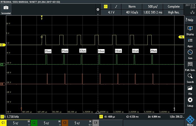
The best resolution I've been able to get from one pass to the next is 2us, despite OCR1A changing only 1 value from the last pass; see attached example graph from my O-scope. I can verify that OCR1A is changing by only 1 by printing it to the serial monitor.

Can anyone explain why my pulse width won't change by a smaller resolution than only 2us when the resolution of my timer is 0.5us?

Thanks!

A note about the structure of my code; I'm using a switch-case structure in a while loop to act as a state machine. When the OCR1A interrupt is triggered, it increments the state of the machine. This is an ambitious project for me (read: I don't have too much experience with things of this scale and I've learned a lot) so I am open to changing the structure of my code to better optimize my time.

Variable control time.gif

So in total, an ISR using the ISR define will take you 2.625 µS to execute, plus whatever the code itself does.

If you use an ISR, you just can not go as fast as you like.

You don't show the code, so this is just a guess.

wooplogic:
Can anyone explain why my pulse width won't change by a smaller resolution than only 2us when the resolution of my timer is 0.5us?

2µsecs is 32 clock cycles on a 16MHz Arduino.

Can the ISR overhead (call and return) and the calculations you want done be carried out in less than 32 clock cycles?

...R

Thanks for the input Whandall and Robin2 but I'm not sure you've understood my question. Each of your responses indicate an 'overhead' that is required to run the ISR of ~2us but the code I need to execute has a minimum of 18us to run. During initial testing, if my test time got below 18us I saw errors due to the overhead of my code and the ISR, as you mentioned. In case 9, I check for that to prevent those errors.

I'm sure a little code would help, see below. I've removed some sections to hopefully make it more readable and get to the question at hand.

//When timer comparison triggers, advance program to next state
ISR(TIMER1_COMPA_vect) {
  tqTestState++;
}

//This while loop is called within a working function within the main loop - note that I use times over 100 as fault codes
while (!testComplete && tqTestTime < 0x0064) {    //0x0064 = 100
    switch (tqTestState) {
      case 0:
        {
          /
          //Setup timer for first stage of test
          //First step is to end 50kHz pulse
          cli();
          TCNT1 = 0x0000;
          OCR1A = 0x0078; //0078 ~= 60us; 3 pulses at 50kHz
          sei();

          digitalWrite(pinQ1Driver, 1);

          //Advance the state
          tqTestState++;
        }
        break;
      case 1:
        {
          // do nothing while waiting for 50kHz to turn off
        }
        break;
      case 2:
        {
          if (condition)
          {
            //pass back error code
          } else {
            //Setup timer for about 1ms total
            cli();
            TCNT1 = 0x0000;
            OCR1A = TIMETOCONDUCT;
            sei();

            //Advance the state
            tqTestState++;
          }
        }
        break;
      case 3:
        {
          // do nothing while waiting for the timer to finish (~1ms)
        }
        break;
      case 4:
        {
          //Advance the state
          tqTestState++;

          //Turn off positive voltage, turn on negative voltage
          digitalWrite(pinQ1Driver, 0);
          digitalWrite(pinQ2Driver, 1);
        }
        break;
      case 5:
        {
          //Wait for negative voltage to appear
          if (digitalRead(pinTurnOffSense)) {
            //Set timer for tq time
            cli();
            OCR1A += tqTestTime;
            sei();
            tqTestState++;
          }
        }
        break;
      case 6:
        {
          //Waiting for timer interrupt to trigger next state

          if (condition) {
            //pass back error code
          }
        }
        break;
      case 7:
        {
          //Timer has triggered and advanced state

          //Turn off negative voltage, apply positive voltage
          digitalWrite(pinQ2Driver, 0);
          digitalWrite(pinQ3Driver, 1);

          //Set time limit to check for positive voltage
          cli();
          OCR1A += 0x0800; // 0x0800 ~1ms
          sei();

          //Advance the state
          tqTestState++;
        }
        break;
      case 8:
        {
          if (condition)
          {
            //set variable to be checked in next state
          }
        }
        break;
      case 9:
        {
          digitalWrite(pinQ3Driver, 0);
          relax();
          testComplete = true;

          if (variable from case 8) {
          // as long as time is greater than the minimum allowed (appox 18us)
            if (tqTestTime > MINTQTIME) {
              tqTestTime -= TQSTEPDOWN;
            } else {
              //minimum tq time reached - highly unlikly with a unit but need to plan for it
              tqTestTime = 0x0064 + (byte)ERRMINTQREACHED;
            }
          }
        }
        break;
      default:
        {
          // this should never run but if for any reason it does, return an error code
          tqTestTime = 0x0064 + (byte)ERRPROGRAMFAULT;
          relax();
          testComplete = true;
        }
        break;
    }
  }

To summarize, each time the while loop runs, the state variable determines what switch statement should run. When the code gets to case/state 5, a time is added to OCR1A - this time is decreased each time the while loop runs until a certain condition is measured. The 'step' decrease is only 1 (0x0001). With the Timer 1 registers set to 1/8th time scale, this should correspond to a decrease of 0.5us. As this test runs, however, the minimum decrease read on the O-Scope is 2us after a few iterations.

Thanks again for any input!

Doing some testing of my own to try to isolate the problem. Wrote the following full code (as stripped down as I can get it with 3 pins) that shows the same phenomenon. If I run this code with a static value of testTime then manually decrement testTime by 0x0001 and reupload, the pulse width changes 0.5us.

volatile int pgrmState = 0;
int ledPin0 = 11;
int ledPin1 = 12;
int ledPin2 = 13;
byte testTime = 0x0060;

ISR(TIMER1_OVF_vect) {
  pgrmState = 0;

  OCR1A = 0x0000;
  TCNT1 = 0x0000;
}

ISR(TIMER1_COMPA_vect) {
  pgrmState++;
}


void setup() {

  TCCR1A = B00000000;
  TCCR1B = B00000010;
  OCR1A = 0x0000;

  TCNT1 = 0x0000;

  TIMSK1 = 0x03;

  pinMode(ledPin0, OUTPUT);
  pinMode(ledPin1, OUTPUT);
  pinMode(ledPin2, OUTPUT);
  digitalWrite(ledPin0, LOW);
  digitalWrite(ledPin1, LOW);
  digitalWrite(ledPin2, LOW);

  sei();
}

void loop() {
  if (pgrmState == 0) {
    digitalWrite(ledPin0, HIGH);
    cli();
    TCNT1 = 0x0000;
    OCR1A = 0x0030;
    sei();
    pgrmState++;
  } else if (pgrmState == 1) {
    // do nothing
  } else if (pgrmState == 2) {
    digitalWrite(ledPin0, LOW);
    digitalWrite(ledPin1, HIGH);
    cli();
    OCR1A += testTime;  //0x0045 ~= 34uS; 0x0038 ~= 25uS; 0x0018 about minimum @ 12u
    sei();
    pgrmState++;
  } else if (pgrmState == 3) {
    // do nothing
  } else if (pgrmState == 4) {
    digitalWrite(ledPin1, LOW);
    digitalWrite(ledPin2, HIGH);
    cli();
    OCR1A += 0x0030;
    sei();
    pgrmState++;
  } else if (pgrmState == 5) {
    // do nothing
  } else if (pgrmState == 6) {
    digitalWrite(ledPin2, LOW);
    cli();
    OCR1A += 0x0030;
    sei();
    pgrmState++;
  } else if (pgrmState == 7) {
    // do nothing
  } else if (pgrmState == 8) {
    testTime -= 0x0001;
    pgrmState = 0;
  }


  if (testTime <= 0x0020) {
    testTime = 0x0060;
  }
}

However, if I run this code with the decrement within the loop, the length the ledPin1 pulse starts around 44us and steps down every 3 or 4 pulses by 2us.

I think you are seeing issues with running the timer in normal mode. The data sheet warns

The Output Compare units can be used to generate interrupts at some given time. Using the Output
Compare to generate waveforms in Normal mode is not recommended, since this will occupy too much of
the CPU time.

In normal mode the timer never stops until the top value of 0xFFFF. Say you program an an interrupt at OCR1A = 100. When the interrupt and the two digitalWrites are complete the counter may be at 112 (2us of processor time for the interrupt, and 2 each for the digtial writes). You then increase OCR1A to 200. Your next interrupt will not be when you expect it.

I would explore doing what you want to do with CTC mode or Fast PWM mode. Let the timer top or ctc value control each event, rather than trying to keep moving OCR1A up as the timer runs.

wooplogic:
If I run this code with a static value of testTime then manually decrement testTime by 0x0001 and reupload, the pulse width changes 0.5us.

However, if I run this code with the decrement within the loop, the length the ledPin1 pulse starts around 44us and steps down every 3 or 4 pulses by 2us.

To save me having to study the Atmega datasheet can you explain how you are using the Timer?

And can you post the equivalent program that has the static value of testTime.

What is not at all clear to me is where, within the Timer cycle, the code to change the value of testTime happens. For example is the Timer stopped, or running through a cycle when that happens?

...R

PS... Maybe @cattledog has put his finger on the issue

Have you turned off timer0 interrupts? You'll lose delay, millis and micros(), since they use the timer0
interrupt. Having other interrupts about will introduce jitter on the timescale of about 4us to ATmega
processors at 16MHz.

Another thing to remember with interrupts is that they only get serviced after the current command is completed, so depending on where you are in your code when the interrupt fires, the act time can vary.

For more precise timing at high speeds I have found it much more reliable to leave a timer/count at no prescale and the compare the elapsed TCNTn with my desired gap. For framing high speed serial you get good results, not possible with interrupts, and good resolution - byte a =TCNT1; while((TCNT1 -a) < 410); gives me a perfect 26us pulse width.

You could use the interrupt to trigger the first event and then time the subsequent events with the counter.

cattledog,
Thanks for the heads up; I missed that in the datasheet. At your suggestion, I'm thinking of how to implement using CTC or fast PWM mode.

Robin2,
Normal mode, 8x multiplier, using only 1 interrupt.
The grand scheme was to use the timer to orchestrate the entire process during a single cycle; from 0x0000 to 0xFFFF. The entire test takes less than 3ms; with a 8x multiplier yeilding a 32ms cycle time, I expected it could be easily done in one cycle. The test starts at 0x0000 setting the first output and the comparator interrupt to trigger the next state approximately 1ms later. In the full code, while waiting for the interrupt I'm checking an input for a test value. After the interrupt the next output state is activated and the next comparator interrupt is set. The three pulses are produced using this technique. In the sample code I stripped out the measurement to make sure that wasn't the problem.

From that last paragraph, you can see testTime is not changed during the timer cycle. testTime is only changed after the last measurement is made (no where near the end of the timer cycle ~3/32ms). See below for the static value example; this version of the code runs the exact same three pulses over and over.

volatile int pgrmState = 0;
int ledPin0 = 11;
int ledPin1 = 12;
int ledPin2 = 13;
byte testTime = 0x0060;

ISR(TIMER1_OVF_vect) {
  pgrmState = 0;

  OCR1A = 0x0000;
  TCNT1 = 0x0000;
}

ISR(TIMER1_COMPA_vect) {
  pgrmState++;
}


void setup() {

  TCCR1A = B00000000;
  TCCR1B = B00000010;
  OCR1A = 0x0000;

  TCNT1 = 0x0000;

  TIMSK1 = 0x03;

  pinMode(ledPin0, OUTPUT);
  pinMode(ledPin1, OUTPUT);
  pinMode(ledPin2, OUTPUT);
  digitalWrite(ledPin0, LOW);
  digitalWrite(ledPin1, LOW);
  digitalWrite(ledPin2, LOW);

  sei();
}

void loop() {
  if (pgrmState == 0) {
    digitalWrite(ledPin0, HIGH);
    cli();
    TCNT1 = 0x0000;
    OCR1A = 0x0030;
    sei();
    pgrmState++;
  } else if (pgrmState == 1) {
    // do nothing
  } else if (pgrmState == 2) {
    digitalWrite(ledPin0, LOW);
    digitalWrite(ledPin1, HIGH);
    cli();
    OCR1A += 0x0045;  //0x0045 ~= 34uS; 0x0038 ~= 25uS; 0x0018 about minimum @ 12u
    sei();
    pgrmState++;
  } else if (pgrmState == 3) {
    // do nothing
  } else if (pgrmState == 4) {
    digitalWrite(ledPin1, LOW);
    digitalWrite(ledPin2, HIGH);
    cli();
    OCR1A += 0x0030;
    sei();
    pgrmState++;
  } else if (pgrmState == 5) {
    // do nothing
  } else if (pgrmState == 6) {
    digitalWrite(ledPin2, LOW);
    cli();
    OCR1A += 0x0030;
    sei();
    pgrmState++;
  } else if (pgrmState == 7) {
    // do nothing
  } else if (pgrmState == 8) {
    //testTime -= 0x0001;
    pgrmState = 0;
  }

//unnecessary with a fixed value of testTime
  if (testTime <= 0x0020) {
    testTime = 0x0060;
  }
}

MarkT,
In the full code, timer0 is used to generate a 50khz pulse. See below for the function written to start that. Since the 50kHz wave is 50% duty cycle with a period of 20us, I didn't expect this to be a contributing factor. The 50kHz signal is used in the first few states but if testing confirms it is a problem, it can be disabled after it's no longer needed.

void start50kHzSignal() {

  cli();

  //Setup 50kHz signal
  // TC0 Control Register A, Sets up output mode and waveform generation mode
  TCCR0A = B01000010;
  // TC0 Control Regsiter B, disables input capture settings, finishes waveform generation mode, sets prescaler value
  TCCR0B = B00101010;
  OCR0A = 0x13;   //0001 0011 Time necessary for 50kHz
  DDRD |= 0x40;   //0100 0000 Enable pin output

  sei();

}

(When I wrote this, I was still getting into the idea of manipulating registers; I should probably clean it up and standardize my format.)

Having said all that, I think it is the structure of the code that is the problem. I've had it in my head to try but DKWatson's reply inspired me to do it. If I replace the huge while loop and switch case with a more straight-forward one-by-one execution scheme with small while loops when I need to wait, I seem to be getting the results I expected. This includes changing the pins by port manipulation instead of using the digitalWrite command. See below.

volatile bool nextState = false;
int testTime = 495;

ISR(TIMER1_COMPA_vect) {
  nextState = true;
}

void setup() {
  TCCR1A = B00000000;
  TCCR1B = B00000001;
  // 0x01E0 = 30us with no scaling
  OCR1A = 0x0000;

  TCNT1 = 0x0000;

  TIMSK1 = 0x03;

  DDRB = 0x38;

  PORTB = 0x00;

  sei();
}
// 0x01E0 = 30us with no scaling
void loop() {

  nextState = false;
  PORTB = 0x08;
  cli();
  TCNT1 = 0x0000;
  OCR1A = 0x0200;
  sei();

  while (!nextState) {
  }
  nextState = false;

  PORTB = 0x10;
  cli();
  OCR1A += testTime;//testTime;  //0x0045 ~= 34uS; 0x0038 ~= 25uS; 0x0018 about minimum @ 12u
  sei();

  while (!nextState) {
  }
  nextState = false;

  PORTB = 0x20;
  cli();
  OCR1A += 0x0200;
  sei();

  while (!nextState) {
  }
  nextState = false;

  PORTB = 0x00;
  cli();
  OCR1A += 0x0200;
  sei();

  while (!nextState) {
  }
  nextState = false;

  cli();
  //testTime -= 0x0010;
  testTime -= 16;
  if (testTime <= 256) {
    testTime = 495;
  }
  sei();
}

I'll updated the full code and report back the results. If anyone has an further thoughts, please post them!

wooplogic:
See below for the static value example; this version of the code runs the exact same three pulses over and over.

That code for the static value does not use the variable testTime at all - it uses a "hard wired" value for OCR1A. That may lead to the compiler producing different code.

That kind of thing can be difficult to debug because the compiler gets in the way. Try it with testTimer declared volatile and then used to update OCR1A - but without changing the value of testTimer within the program. I believe the use of volatile will prevent the compiler from optimizing away the variable.

...R

Heed Robin2.

I've just gone through a 5 day nightmare trying to figure out why the (almost) exact same code was giving me different results with interrupt timing. An hour ago I stuck #pragma GCC optimize ("-O0") at the top and all the problems went away.

Robin,
Sorry, "static" was a poor word choice on my part.

DKWatson,
Your post is the first time I've seen the #pragma directive. After doing a little research, would anyone suggest using the following example to shield just the critical function from optimization?

#pragma GCC push_options
#pragma GCC optimize("O0")
void myTest() {
// doing stuff
}
#pragma GCC pop_options

Update:
I updated the primary code using the structure mentioned in my last post and I've gotten favorable results!

So you don't turn off the timer0 interrupt, but instead arrange that it happens every 20us?

Has anyone got a link to an explanation of #pragma and its usage?

...R

MarkT:
So you don't turn off the timer0 interrupt, but instead arrange that it happens every 20us?

Timer 0 is configured to produce a 50kHz 50% duty cycle signal on pin 6. The only manipulation of Timer 0 is in the previously posted function, start50kHzSignal(). This function is called within the setup function after a couple other initialization steps.

Yes, as I said you haven't turned off the timer0 ISR that implements delay(), millis() and micros(), but you
have made the timer0 ISR run 50 times more often. That's going to create distinct jitter in your ISR's timing
of the order of 4µs or so as I've previously mentioned, as well as stealing about 20% of your CPU time.

If you're going to repurpose timer0, have a look at the implementation of millis(), micros() and delay() in
the source, you'll see that its setup to interrupt on timer0 overflow. You've not undone that.

Having said all that, I think it is the structure of the code that is the problem. I've had it in my head to try but DKWatson's reply inspired me to do it. If I replace the huge while loop and switch case with a more straight-forward one-by-one execution scheme with small while loops when I need to wait, I seem to be getting the results I expected. This includes changing the pins by port manipulation instead of using the digitalWrite command. See below.

I really can not see how changing from switch case to while (!nextState) is improving timing, since the case or the nextState is being set with the same compare interrupt method. Perhaps the blocking method of the while statement is preventing some other aspect of your program from interacting with the timing.

Possibly the major effect was due to eliminating the digitalWrite() for port manipulation.

The pragmas are discussed in the C Preprocessor doc

but the actual directives/attributes are scattered all over the gcc manual

Try starting in section 6.31 and making your way to 6.62.

DKWatson:
The pragmas are discussed in the C Preprocessor doc

Many thanks.

...R