I just posted the code.
Post a schematic diagram of the system, with all parts, pins and connections clearly labeled.
I just posted the code.
Post a schematic diagram of the system, with all parts, pins and connections clearly labeled.
I understand and very much appreciate your recommendation. However, I am trying to develop a self-contained piece of SW that does not require a library outside what's provided by the Arduino IDE. This is a learning project in progress, with next phase being to develop a flight controller or something to that effect. Hence, the desire (...) to develop the SW myself. Wish me luck s.v.p.
Is there a software that makes it easier to draw schematics. I'm not an EE/CS/CE, so I mean an app. that we lay people can learn quickly and have access to.
You can take a photo of a hand drawn schematic and drop it here.
No, the easiest and fastest method is still pencil and paper.
I appreciate that and do wish you luck.
I will only say that if you are hoping to end up actually flying something, you probably should stop all efforts to get N channels of PWM decoded, and prolly even not bother with PPM.
Modern r/c serial protocols are superior, and there's no good reason to put yourself at what would be a disadvantage, no matter how slight, when it comes to the manner in which you control the vehicle from your remote location.
Coding to a serial protocol will def be as useful for growth as a programmer.
As the any libraries, I usually like to DIY the same functionality, or the parts of it I need. Library code runs the gamut from terrible to wonderful as a learning source; sometimes reading through it can be instructive.
a7
good day,
the output of your receiver gives a constant PWM pulse, which is translated by a servo to the angle that needs to be turned. Read the following article (Servo Tutorial - How a Servo Works), I think it will become more clear.
Back at ya.
What you say is true but part of the story. One way of using the receiver is using its multiple PWM signal outputs, of which the OP seems aware and is attempting to read using the Arduino.
She does not seem to know or has chosen not to pursue use of the two other means of acquiring the transmitted data, the PPM output and the IBUS serial signal.
And let's hope any of those is not constant. I know you meant constantly reporting the received value whether it changed from last time or no.
a7
I don't use a servo, only use transmitter + receiver + Arduino UNO + sketch.
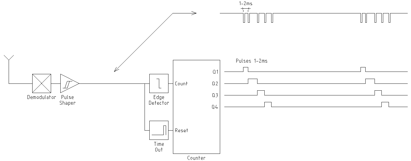
I do not understand this drawing. I do not have an EE background, sorry.
It’s the old fashioned, analog stuff. The drawing shows function blocks and signals at several points. It was designed with a minimum of components, to reduce weight as well as power consumption.
It’s possible that modern digital stuff may work slightly different, but any analog servo connected to one of the outputs still requires an update of it’s signal repeatedly. And your ISR will be triggered every time.
Your ISR is unnecessary complicated and slow. Look at this one.
/* To read signals from RC receiver with Arduino UNO R3
CH1 is connected to Arduino pin 8 (PB0)
CH2 is connected to Arduino pin 9 (PB1)
CH3 is connected to Arduino pin 10 (PB2)
CH4 is connected to Arduino pin 11 (PB3)
*/

volatile int ch1duration;  // calculating indexes for arrays takes a lot of time
volatile int ch2duration;
volatile int ch3duration;
volatile int ch4duration;

void setup() {
  PCMSK0 |= 0b00001111;  // enable PinChange interrupt on pins PB0..PB3 in one instruction
  PCICR |= 0b00000001;   // enable PinChange interrupt on port B
}

void loop() {
  // put your main code here, to run repeatedly:
}

ISR(PCINT0_vect) {
  unsigned long presentTime = micros();
  byte presentInputs = PINB;

  static byte previousInputs = 0;  // static variables, initialized outside ISR
  static unsigned long ch1up = 0;
  static unsigned long ch2up = 0;
  static unsigned long ch3up = 0;
  static unsigned long ch4up = 0;

  byte edgesUp = presentInputs & ~previousInputs;  // bitwise AND takes only 1 clockcycle
  if (bitRead(edgesUp, 0)) ch1up = presentTime;    // bitRead() is compiled to 1 machine instruction
  if (bitRead(edgesUp, 1)) ch2up = presentTime;
  if (bitRead(edgesUp, 2)) ch3up = presentTime;
  if (bitRead(edgesUp, 3)) ch4up = presentTime;

  byte edgesDown = ~presentInputs & previousInputs;
  if (bitRead(edgesDown, 0)) ch1duration = presentTime - ch1up;
  if (bitRead(edgesDown, 1)) ch2duration = presentTime - ch2up;
  if (bitRead(edgesDown, 2)) ch3duration = presentTime - ch3up;
  if (bitRead(edgesDown, 3)) ch4duration = presentTime - ch4up;

  previousInputs = presentInputs;
}
The important thing to see in the diagram is the sequential nature of the N outputs.
Your code needlessly assumes that any channel might show a pulse at any time; in fact due to the simplicity of 20th century electronics only one pulse must be measured at a time. Thus the much simpler code @stitech presents.
That said, I stay with my recommendation to skip to the 21st century and use a serial protocol when one is available.
a7
The sytem OP uses is a digital one.
The PWM outputs of an Arduino all go high at the same time.
My ISR will work with that too.
It will even work if channels 1, 4, 2 and 5 are measured.
Two things good to know, THX.
a7
Thanks very much for taking the time to write this code. I'll work on it and let you know. Incidentally, by // put your main code here, to run repeatedly: in loop() you mean to execute what in there??
TheISR appears to maintain these global variables
volatile int ch1duration;
volatile int ch2duration;
volatile int ch3duration;
volatile int ch4duration;
with which you are free to do with whatever you need. You could print them just to see the ISR working, for a start.
Note: multi-byte variables used in ISRs and non-ISR code both need to be accessed carefully. most ppl make their own copy by doing something like
  noInterrupts();
  int myCopy = ch3duration;
  interrupts();
and going on to use myCopy instead of ch3duration.
Name it better. 
a7
Thank you for your code. Unfortunately, as far as I have tested it, your ISR does does not provide the PWM results I was getting with my previous version. When I print ch1duration, ch2duration, ch3duration, ch4duration, they are all zero. Also, one of the accepted recommendations for ISR writing is to use volatile global variables, is there any reason why you did NOT??