IR activated light switch - residual bugs

Hello,

I could use some help with two residual bugs in my current "side project"...

I've been working on an IR sensor activated light switch the last two weeks or so, and the project is nearly finished, except for migrating it from a breadboard to a perfboard and soldering everything together.

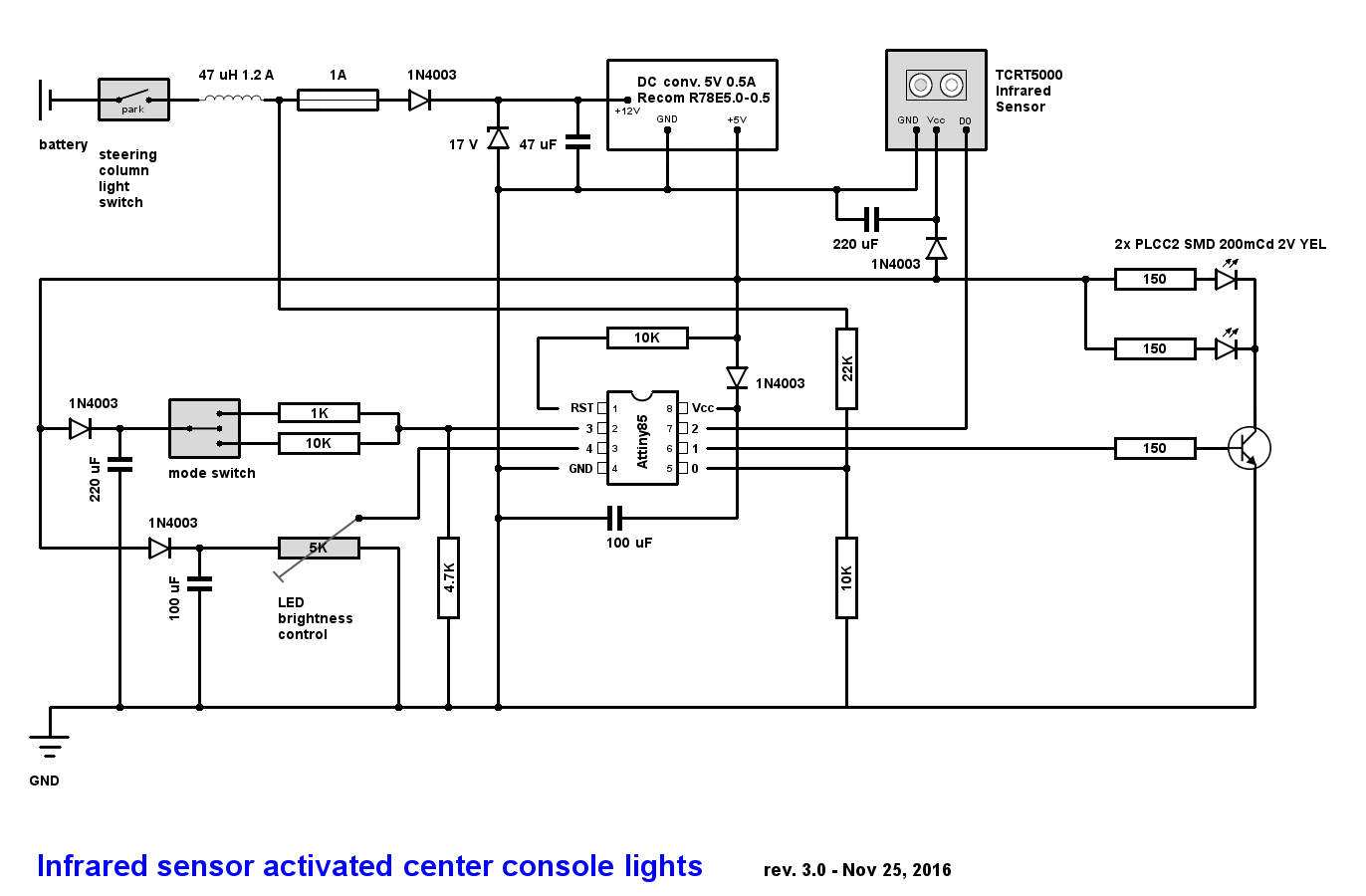
With this light switch circuit, I want to illuminate a compartment in my car's center console that has no lighting, but it would be practical to have one there. So I've made a circuit with three modes that are switched with an "on-off-on" rocker switch - one mode is "always-on", then there's an "always-off" mode, and finally, an IR sensor activated mode using a TCRT5000, which switches the light on for ten seconds when the IR sensor picks up movement and then fades it out again. The lights will be dimmed up and down using PWM. The brightness can be adjusted through a pot, which is read by the Attiny and then translated into a cycle duty value between 0 and 255 to set the brightness via analogWrite.

Here's my circuit:

And here's my code... please note that as far as pin definitions, I am developing the code on an Atmega328P-PU, because that kind of makes it easier to debug; the final version of it will indeed be ported to and run on an Attiny85-20PU.

// Pin definitions
#define ledPin1 5
#define ledPin2 6
#define IRpin A1
#define switchPin A0
#define brightnessPot A2

// Brightness variables
volatile boolean lightOn = false;
int brightness = 0;
float ledMaxBrightness;
int ledMaxBrightnessSet;

// Timer variables
volatile unsigned long timerStart;
volatile unsigned long timeDifference = 0;
volatile unsigned long timeNow = 0;

// Setting maximum brightness according to brightness pot value
int getMaxBrightness() {

  ledMaxBrightness = (float) analogRead(brightnessPot) / 1023;
  ledMaxBrightnessSet = (int) (ledMaxBrightness * 255);

  if (ledMaxBrightnessSet < 5) ledMaxBrightnessSet = 5; // Eliminating electrical noise on the pin
  return ledMaxBrightnessSet;
}

// Dimming up the lights...
void dimUp() {

  int delayFactorUp = (int) (3000 / analogRead(brightnessPot)); // The higher max brightness, the faster the dim up...

  for (brightness = 0; brightness < getMaxBrightness(); brightness++) { // Dimming up the lights

    analogWrite(ledPin1, brightness);
    analogWrite(ledPin2, brightness);
    delay(delayFactorUp);
  }
  lightOn = true;
}

// Dimming down the lights...
void dimDown() {

  int delayFactorDown = (int) (5000 / analogRead(brightnessPot)); // ...and the same for dimming down

  for (brightness = getMaxBrightness(); brightness >= 0; brightness--) { // Dimming down the lights

    analogWrite(ledPin1, brightness);
    analogWrite(ledPin2, brightness);
    delay(delayFactorDown);
  }
  lightOn = false;
}

void setup() {

  Serial.begin(9600);
  pinMode(IRpin, INPUT);
  pinMode(ledPin1, OUTPUT);
  pinMode(ledPin2, OUTPUT);
  pinMode(switchPin, INPUT);
  pinMode(brightnessPot, INPUT);
}

void loop() {

  // IR activated mode
  if (analogRead(switchPin) > 800) {
        
    if (!digitalRead(IRpin) && !lightOn) dimUp(); // The IR pin goes to LOW (!) when the sensor is tripped

    if (digitalRead(IRpin) && lightOn) {

      timerStart = millis();
      timeDifference = 0;

      while (timeDifference <= 10000) {

        timeDifference = millis() - timerStart;
        analogWrite(ledPin2, getMaxBrightness());

        if (analogRead(switchPin) < 800 || !digitalRead(IRpin)) break;
      }
      if (timeDifference >= 10000) dimDown();
    }
  }

  // always-on mode
  if (analogRead(switchPin) < 800 && analogRead(switchPin) > 100) {

    if (!lightOn) dimUp();
    analogWrite(ledPin2, getMaxBrightness());
  }

  // always-off mode
  if (analogRead(switchPin) < 100 && lightOn) dimDown();
}

Now, this code is nearly finished and runs reasonably well; but it still has two bugs that just drive me nuts.

One is this here, in the function getMaxBrightness():

if (ledMaxBrightnessSet < 5) ledMaxBrightnessSet = 5;

The brightness adjustment using the pot works very well, but whenever I turn the pot down so that the analog input reading does go below 5 and then switch to a different mode, the IC gets stuck and I cannot dial the brightness up again. And the LEDs can't be switched off anymore either using the switch, only a reset helps.

The second one is that in "IR activated mode", the LEDs are supposed to be off when I initially put the mode switch in that position. Only when the sensor is tripped should the LEDs dim up. But about every other time, when I switch to IR activated mode, the lights go on without the sensor being tripped:

if (!digitalRead(IRpin) && !lightOn) dimUp();

(as in the code above, IR pin on LOW means the sensor is activated!)

Strangely, when I print out the IR sensor's state via serial using Serial.println(digitalRead(IRpin), it always comes back as "1". So that should kind of rule out that the lights would dim up anyway. But that's not what is happening.

It'd be great if you could help me fix this.

Cheers,

carguy.

nobody? :frowning:

I don't see anything in your code that deals with interrupts, so the volatile decoration is useless.

  if (analogRead(switchPin) > 800) {

To me, a switch pin is one that has a switch attached to to. A switch is a digital device - it is either on or off. Using analogRead() to read the voltage coming from a device that either provides 0V or 5V does not make sense. What, exactly, is connected to this pin? Why is it called switch pin?

int getMaxBrightness() {

  ledMaxBrightness = (float) analogRead(brightnessPot) / 1023;
  ledMaxBrightnessSet = (int) (ledMaxBrightness * 255);

  if (ledMaxBrightnessSet < 5) ledMaxBrightnessSet = 5; // Eliminating electrical noise on the pin
  return ledMaxBrightnessSet;
}

Converting a value from the range 0 to 1023, to a range of 0.0 to 1.0, and then converting a value in that range to a range of 0 to 255 does not make sense.

Just divide the analog reading by 4. One step, no floating point arithmetic needed. Constraining the minimum end of the range does NOT eliminate noise. That comment is wrong.

The second one is that in "IR activated mode", the LEDs are supposed to be off when I initially put the mode switch in that position.

This sounds like you need to read and understand the state change detection example. Something should happen when the switch changes state, not when the switch is in some state.

PaulS:
To me, a switch pin is one that has a switch attached to to. A switch is a digital device - it is either on or off. Using analogRead() to read the voltage coming from a device that either provides 0V or 5V does not make sense. What, exactly, is connected to this pin? Why is it called switch pin?

The switch pin is connected to the mode switch in my schematic. Again, I know things are made a bit complicated by the fact that I am developing this code on an Atmega328 but will use it on an Attiny85 as pictured in the schematic. So the pin assignments in the code aren't (yet) what they are in the schematic.

But anyway, the "switch pin" is connected to the "on-off-on" rocker switch. As you can see in my schematic (where switchPin is on pin 3 of the Attiny instead of pin A0 as in my code thus far), I've wired it up so that it puts different voltages onto the switch pin depending on the switch's position. Essentially, I've got a dual voltage divider there. In the "IR mode" position, it gives a voltage of just over four volts, which is interpreted as somewhere around a value of 931 using analogRead. And then the "always-on" position gives an analog value of around 531. So I am using 800 as a roundabout cutoff between the two modes. And then in the "off mode", the voltage is zero, but to be safe, I am setting an analogRead value of 100 as a cutoff for the device to get into "off mode".

This part of my code has been working without a fault. Operating the switch very reliably makes the Attiny execute whatever code is contained in the pertaining if statement.

I am doing this because the way my circuit works, I will only have one free pin on the Attiny85 to connect to the mode switch. I could just connect both LEDs to one pin and thus be left with two pins to connect to the mode switch, but the LEDs already draw up to 20 mA each. Yes, that makes 40 mA altogether for which the Attiny is built according to its spec sheet, but I am guessing it can't hurt to play it safe.

PaulS:
Converting a value from the range 0 to 1023, to a range of 0.0 to 1.0, and then converting a value in that range to a range of 0 to 255 does not make sense.

Just divide the analog reading by 4.

Yeah, that bit was slightly nonsensical... wonder why I didn't think of that before... :slight_smile:

However, I just tried that. Now the Attiny freezes up the same way when I've got the pot set to zero.

PaulS:
This sounds like you need to read and understand the state change detection example. Something should happen when the switch changes state, not when the switch is in some state.

But again, I am guessing "state change" won't help me much if my code relies on reading analog input values from that switch?

Also, in "IR mode", the LEDs are supposed to go on not depending on the switch's position, but depending on the state of the IR sensor and on whether the lights have already been turned on:

  if (!digitalRead(IRpin) && !lightOn) dimUp(); // The IR pin goes to LOW (!) when the sensor is tripped

Using a switch like that is fine. But I see a tiny error in the code. But because of the high thresholds it's probably not a problem. What happpens when the switch IS 100? Would have been easy to solve by using if, else if, else

int value = analogRead(SwitchPin);
If(value > 800){

}
//already know it's below 800
else if(value > 100){

}
//must be below 100
else{

}

Also just read it once because if you are really unlucky and you change is exactly between two reads you might think you're in another state then you really are.

And for the second problem, what if you switch between always on and IR mode? The lights are on from the always on mode. So both conditions. And if the sensor isn't tripped

    if (digitalRead(IRpin) && lightOn)

is true when you go into that mode :wink: So if you don't want that you need to check if you go into that mode. And if so, be sure to turn off the light.

And that while-loop in IR-mode is almost a delay(). Only difference is that you update the brightness in the mean time if you turn the pot. But it IS blocking code. Just like your fade up and down functions. Normally it's best to let the loop run free, don't use delay, and do the things you need to do when you need to do them.

And if I may suggest, in my signature I have an easy library to control do all the fading in a non blocking way. Would make the code very easy :wink:

septillion:
Using a switch like that is fine. But I see a tiny error in the code. But because of the high thresholds it's probably not a problem. What happpens when the switch IS 100? Would have been easy to solve by using if, else if, else

int value = analogRead(SwitchPin);

If(value > 800){

}
//already know it's below 800
else if(value > 100){

}
//must be below 100
else{

}

True... I'll change that. :slight_smile:

septillion:
And for the second problem, what if you switch between always on and IR mode? The lights are on from the always on mode. So both conditions. And if the sensor isn't tripped

    if (digitalRead(IRpin) && lightOn)

is true when you go into that mode :wink: So if you don't want that you need to check if you go into that mode. And if so, be sure to turn off the light.

The rocker switch is designed so that to get from one "ON" position to the other, you always have to go via the "off" position in the middle:

A switch reading below 100 automatically triggers dimDown(), which also contains lightOn = false. So the lights are automatically turned off every time you switch between the two "on" modes.

septillion:
And that while-loop in IR-mode is almost a delay(). Only difference is that you update the brightness in the mean time if you turn the pot. But it IS blocking code. Just like your fade up and down functions. Normally it's best to let the loop run free, don't use delay, and do the things you need to do when you need to do them.

hm... but being that the code for this switch is fairly simple, to my understanding, it doesn't actually block any code... because all the sketch does is dim the lights up and down and sustain them for ten seconds after the IR sensor was last tripped (this IR sensor has no built-in delay, unlike many PIR motion sensors). And within the while loop, if (analogRead(switchPin) < 800 || !digitalRead(IRpin)) break; ensures that the Attiny will still register when either the IR sensor is tripped again (in which case, another new ten-second delay starts) or the mode switch is turned to "off".

septillion:
And if I may suggest, in my signature I have an easy library to control do all the fading in a non blocking way. Would make the code very easy :wink:

Thanks... I'll look into that. Does your library also run on an Attiny85?

carguy:
The rocker switch is designed so that to get from one "ON" position to the other, you always have to go via the "off" position in the middle:

True, but what if you just switch it from I to II (or other way round)? The Arduino might not read the ADC in that 0 moment. So it does not dim first.

Or, when you switch while it is dimming it will certainly not read the switch because the dimming code is blocking :wink:

carguy:
hm... but being that the code for this switch is fairly simple, to my understanding, it doesn't actually block any code...

Here it's for most part (except for what I wrote above) not a big point it's blocking but it IS blocking code. If you decide you want to do something wile dimming it's not possible now.

carguy:
if (analogRead(switchPin) < 800 || !digitalRead(IRpin)) break;
ensures that the Attiny will still register when either the IR sensor is tripped again (in which case, another new ten-second delay starts) or the mode switch is turned to "off".

It fixes that indeed but not the checking during dimming. Also, it's a bit of a hack... Now you have to read the switch in another place as well.

carguy:
Thanks... I'll look into that. Does your library also run on an Attiny85?

I can confirm that. Tested it on a Digispark which uses a ATtiny85 :slight_smile:

I still have some ideas for the library. Adding gamma correction is high on the list. But it already does everything you do now / what. But I might give that library an update in the next month.

septillion:
True, but what if you just switch it from I to II (or other way round)? The Arduino might not read the ADC in that 0 moment. So it does not dim first.

Or, when you switch while it is dimming it will certainly not read the switch because the dimming code is blocking :wink:
Here it's for most part (except for what I wrote above) not a big point it's blocking but it IS blocking code. If you decide you want to do something wile dimming it's not possible now.

hm... you're right... I just checked what happens if I switch very fast between the II (IR mode) and I (always-on mode) positions of the switch... the code's behavior when I switch quickly enough is that the light dims down and then dims up again.

Maybe this has marginal relevance in daily life, where I will probably only leave the switch on the "IR mode" setting most of the time anyway. But if you're doing it, you might as well do it neatly enough that that doesn't happen... :wink:

septillion:
It fixes that indeed but not the checking during dimming.

Yep, as I just found out.

carguy:
But if you're doing it, you might as well do it neatly enough that that doesn't happen... :wink:

My idea as well. Because you might be good now it's no guarantee it will never happen.

For a start, I would separate the switch checking and the tasks.
A bit of pseudo code / framework

const byte SwitchPin = A0;

byte state; //0 = always off, 1 = always on, 3 = IR


byte getSwitchState(){
  int value = analogRead(SwitchPin);
  if(value < 100){
    return 0;
  }
  else if(value < 800){ //although if would do the same herre because return breaks out
    return 1;
  }
  else{
    return 2;
  }
}

void setup(){
  state = getSwitchState();
  
}

void loop(){
  //read switch
  byte newState = getSwitchState();
  
  //check if it's different then what we had
  if(newState != state){
    state = newState;
    
    //now do the stuff we need to do when entering a state
    //for example:
    if(state == 0){
      turnOffLight();
    }
    else if(state == 1){
      turnOnLight();
    }
    else if(state == 2){
      if(digitalRead(IrPin) && lightIsOn){
        turnOffLight();
      }
    }
  }
  
  //now do the stuff in a state
  //but all there is is the IR checking
  if(state == 2){  
    if(!digitalRead(IrPin)){
      turnOnTime = millis();
      turnOnLight();
    }
    
    if(millis() - turnOnTime > timeInterval){
      turnOffLight();
    }
  }
  
  //and more general for the brightness
  if(lightIsOn){
    setBrightness(analogReadEtc());
  }
}

Hello again,

Unfortunately, I have had very little time lately to move the project forward by much... I've started implementing septillion's library, but my code is still "in the making". Nothing that's really ready to post here yet.

I've given the hardware configuration some thought though.

The circuit will be powered by the car's parking lights loom, for which I will tap straight into the steering column light switch. Which should be no problem because the parking lights go through a 5A fuse.

At the moment of turning the ignition, the X-relay in a car will briefly shut off power to anything that isn't needed to start the engine, because the starter needs to draw a considerable amount. You will also commonly notice this when your car radio briefly cuts out. This can go on for as long as the starter needs to actually start the engine.

So if I turn the ignition over while my circuit's center console LEDs are on, there could be an interruption of power which would cause the LEDs to go out for the duration of the starter turning over. Or if the LEDs are tripped in IR sensor mode, then they would go out and stay out.

Now my idea is to put capacitors into my circuit both for the mode switch and the IR sensor (I haven't yet measured the current that the IR sensor draws). So that the circuit will be able to power itself while the starter draws power away from it.

What do you think of this schematic, which I hope will address all this? Will the capacitors be enough?

I'm thinking that it can't hurt to give the mode switch a 220 uF cap, because much about the circuit and the code depends on analog readings from that switch. I've also given the Attiny itself a much bigger capacitor than is recommended (and also because I've got a whole strip of unused 100 uF caps here :slight_smile: ), but again, this is for a car, with the above mentioned power supply issues.

If you power the leds from the uC like in the schematic all the caps in the schematic will not help you much.... The leds will drain all the caps in an instant.

Keeping the leds on while cranking seems a bit silly to me. You would need some serious capacity. But return to the state before the crank would indeed be nice. But for this, only give the uC (and switch) a cap (via a diode to decouple them from the rest). But to not power the leds from that cap, connect them between a pin and Vcc (aka, sink them). This way the uC keeps on running while cranking. The uC takes just a little bit of current so no huge cap needed to do so.

And if you add a transistor for the leds to free a pin, you could use that pin to detect the power loss due to cracking (simply connect it before the decouple diode) and when the cracking is done (aka, power comes back) you could fade in again.

PS. mm, some interesting differences between American and European lights... What you call parking lights (first click of light switch) is what we call in Dutch stadslicht (citylights) or standlicht in German (stand still lights) and use a different symbol for that. Parking light is those lights only on one side of that car (but not all cars have it, in that case, the stadslicht is used). Same symbol as the American but most of the time with an arrow indicating the side (can be the corresponding indicator light, not blinking).

And from the wiki when talking about the European parking light:
"This function, which is optional under UN and US regulations, is served passively and without power consumption in the United States by the mandatory side marker retroreflectors."
Yeah, right, reflectors. Because everybody knows they are as visible as a real light right.....

Ok, so I have given the circuit schematic a major overhaul today:

I have to say it is beginning to feel a little overengineered considering it's for the simple purpose of lighting a center console compartment... but on the other hand, why not do it that way just because you can... :slight_smile:

I've tried to take your suggestions on board, as I hope you can see.

The TCRT5000 IR breakout will probably need a 220 uF cap because it has two status LEDs on it that draw power. It has a Texas Instruments LM393 comparator on board, I'm not sure what that draws, or how much the actual IR sensor draws.

I'm not really sure yet what to do with the voltage sensing on pin 0... I am going to have to measure exactly how the power supply to the parking light switch behaves while the starter is turning. Maybe I will just do a digitalRead on that pin, and then fade the lights out and back on a little quicker than usual.

septillion:
PS. mm, some interesting differences between American and European lights... What you call parking lights (first click of light switch) is what we call in Dutch stadslicht (citylights) or standlicht in German (stand still lights) and use a different symbol for that. Parking light is those lights only on one side of that car (but not all cars have it, in that case, the stadslicht is used). Same symbol as the American but most of the time with an arrow indicating the side (can be the corresponding indicator light, not blinking).

I'm German btw... :wink: Yes, we call it Standlicht, and you're right, in German, we usually think of it as all the low-power light bulbs in the headlamps and the taillights switched on. I think we use the word "Parklicht" for when one side of the lamps is on. But I have really had to think about that right now... :slight_smile:


EDIT: The IR breakout really consumes a bit of power. I've tried putting in the biggest cap I've got here, which is a 3300 uF cap, and even that appears to just barely keep the board alive for about one second when I switch off Vcc.

Maybe I won't even need to maintain a power supply to the IR breakout. After all, my code has a 10-second sustain built in for the LEDs everytime the sensor is tripped.

But maybe the 3300 uF cap will come in handy elsewhere; if I want to briefly fade out the LEDs while the ignition is turning over, then the LEDs are going to need a power source. So maybe if I put a 3300 uF cap between Vcc and the LEDs?

Also, aside from what the circuit will be supposed to do while the starter is turning over, the LEDs will have to be faded out everytime I simply turn off the parking lights.

EDIT #2:

Here's another overhaul of the schematic, this time with a 3300 uF cap in place:

carguy:
I have to say it is beginning to feel a little overengineered considering it's for the simple purpose of lighting a center console compartment...

Yeah, you are :stuck_out_tongue:

Not to disappoint you, but you can forget powering anything with an LED on it while cranking... Although we call them low power there consumption is HUGE compared to a micro... 3300uF @ 5V will not last that long with 2 leds. I bed it's drained before the car is started and while starting it will drain pretty quick and you will be able to see that right away. So I wouldn't put any effort in powering it and just let them turn off (but fade them in again once started). And if you want to put effort in it, I would use a current source and connect them directly to the 12V. But even then it only takes 0,8 seconds to drain the cap (3000uF, 28mA, starting at 12V, ending at 5V (3V led + 2V constant current circuit) => ( (Ustart - Uend) * C) / I = t => ( (12V - 5V) * 3300uF) / 28mA = 0,825s....)

And then the thing I find the weirdest and most over-engineered. Why use a diode and cap for each component? Just use a single decoupled rail for the micro, the switch and the pot.

But, to do that I would increase all the resistor values. They are all pretty low, I would at least go an order higher. So for the switch 10k, 100k and 47k. For the pot I would use something like a 100k. Both you can help a bit by adding a decoupling cap of 100nF to them. And for detecting voltage I would increase them to 220k and 100k.

Talking about decoupling caps, that's what i miss in the circuit. It's mandatory to add a decoupling cap (100nF ceramic) to each chip. So a 100nF close to the ATtiny is the least you can do. The IR sensor is a module so probably already has one. And like I said, one on the pot and switch line (so after them, not in front) can help them.

I don't know what the IR sensor draws so don't know how easy it is to keep it powered. But with led's on it it will draw the cap very quick. So to have any change to keep it powered, remove the leds.

The base resistor you use is very low, I would say to low. I would increase it to 1k.

About detecting the voltage, I would move the diode in the supply to after the fuse. And move the detection to after the fuse (between fuse and diode). The first because that way you don't measure the voltage across the 47uF (although I don't really think that cap really does something..) and the second because you don't want power to any part of the circuit if the fuse blows :wink:

Hello again,

sadly, I really don't have much time at the moment to move this project forward at a meaningful pace. But I have made some of the changes to the schematic that you suggested.

I haven't yet changed the resistor values for the mode switch and the LED brightness pot, because I haven't had time to buy new resistors. As soon as I get around to that, I will verify on my breadboard that the circuit works with them and then also update the schematic.

If you look at this and the last schematic, the IC does have a decoupling cap, right at the bottom of it. I've put 100 uF in my schematic for the time being, because I also used a 100 uF in another in-car circuit and it works well.

I'm toying with the idea that it would be easier if I power the circuit itself with +12V straight from the car battery, and then use the car's light switch (i.e. the wire in the center console that illuminates various switches and controls) simply as a signal to work out what the LEDs should do at any given point. Also, to reduce power consumption when the car is not in use, the IR module will be switched by the illumination wire using another BC548C. This seems like a good idea to me because it will mean less quiescent current draw when the car is not in use (this is my second car, and during the winter months, I often don't drive it for a month at a time).

Also, if I power the whole circuit via the illumination wire, the problem will be that the lights won't fade out when I turn off the car's light switch, but they will go out much more abruptly, as you said, because 3300 uF isn't much when powering LEDs. For now, I've left the 3300 uF cap in place, because even if it only keeps the LEDs lit for 0.8 seconds, that can be nearly enough to just about bridge the brief power loss during cranking. I've also put in a 10 uF cap over the signal input on pin 0, so that a very brief voltage drop on the illumination wire (bad connection or whatever) will not cause the light to dim up again.

As I said, my actual code is working nicely and is doing what it should now, but maybe it also can't hurt to implement a sleep function on the Attiny, so power consumption will be even less. The voltage regulator itself has a certain quiescent consumption, I think it's around 7 mA.

The 47 uF cap across the regulator is strongly recommended in its data sheet, so that's why I put it in there.

carguy:
sadly, I really don't have much time at the moment to move this project forward at a meaningful pace.

Doesn't matter, I'm busy myself. Just post here to get my attention when you have a question and I'll see it in my update list. :slight_smile:

carguy:
But I have made some of the changes to the schematic that you suggested.

See a lot of changes, non I suggested.....

carguy:
I will verify on my breadboard that the circuit works with them and then also update the schematic.

It will work, Ohm's law still applies :wink: And you're not the first to do it :wink:

carguy:
I've put 100 uF in my schematic for the time being, because I also used a 100 uF in another in-car circuit and it works well.

100uF is by no means a decoupling capacitor. It's value is wayyyyyyyyy to big to act fast. (probably a electrolytic cap?) It's a buffer capacitor. 100nF ceramic is a decoupling capacitor.

carguy:
I'm toying with the idea that it would be easier if I power the circuit itself with +12V straight from the car battery,

I think using a permanent 12V would make it easier but I would not tap it of the battery directly. Just find a place with permanent 12V on it, for example the interior light or before the light switch (because you are already tapping that).

carguy:
and then use the car's light switch (i.e. the wire in the center console that illuminates various switches and controls) simply as a signal to work out what the LEDs should do at any given point.

Also nice idea. But the implementation is a bit overkill.... I would just use a voltage divider and a decoupling cap.

carguy:
Also, to reduce power consumption when the car is not in use, the IR module will be switched by the illumination wire using another BC548C. This seems like a good idea to me because it will mean less quiescent current draw when the car is not in use (this is my second car, and during the winter months, I often don't drive it for a month at a time).

Keep in mind the D0 wire of the module will now give you weird signals when it's off. Probably Vcc.You have to compensate in code.

And uhhh, if you don't drive a car for more then a month, especially in winter, it's a really really good idea to connect it to a trickle charger. You're battery will thank you :wink: (by lasting longer...)

carguy:
Also, if I power the whole circuit via the illumination wire, the problem will be that the lights won't fade out when I turn off the car's light switch, but they will go out much more abruptly, as you said, because 3300 uF isn't much when powering LEDs.

Yep.

carguy:
For now, I've left the 3300 uF cap in place, because even if it only keeps the LEDs lit for 0.8 seconds, that can be nearly enough to just about bridge the brief power loss during cranking.

Two buts:

  • Does your car start and restore power within 1 second? Damn...
  • Without constant current source the leds will fade down quite noticeable while cranking and will fade up quickly when power is restored. This will be very noticeable.

carguy:
I've also put in a 10 uF cap over the signal input on pin 0, so that a very brief voltage drop on the illumination wire (bad connection or whatever) will not cause the light to dim up again.

Just do that is software. much easier :wink:

carguy:
but maybe it also can't hurt to implement a sleep function on the Attiny, so power consumption will be even less. The voltage regulator itself has a certain quiescent consumption, I think it's around 7 mA.

You can do that but with a quiescent current of 7mA of the regulator I would not bother....

carguy:
The 47 uF cap across the regulator is strongly recommended in its data sheet, so that's why I put it in there.

Cap is indeed recommended in the datasheet but I see something in the range of 4,7uF to 10uF... Don't know why they recommend it especially for low impedance sources... A normal battery is a pretty high impedance source and then a cap would make more sens... So think it's a typo. Don't think you need it here tho, a car battery is not a regular battery, but it will not hurt.

PS Tip when drawing, make more use of the GND symbol and try to draw things connected to power or GND vertical with power on top and GND below. Makes it easier to read.
PSS Your battery is missing a GND symbol :wink:

septillion:
I think using a permanent 12V would make it easier but I would not tap it of the battery directly. Just find a place with permanent 12V on it, for example the interior light or before the light switch (because you are already tapping that).

I could use the permanent 12V supply of the radio. It's got a 2mm² wire, so I am sure it would be able to handle a few more milliamps.

septillion:
Keep in mind the D0 wire of the module will now give you weird signals when it's off. Probably Vcc.You have to compensate in code.

The IR sensor always gives out 5V on the D0 line, except for when you hold your hand in front of it. Yes, I've checked and it also gives out 5V when I switch off the power supply that switches the transistor in my schematic. But again, D0 only goes to 0V when the sensor is triggered, which means whenever there's 5V on D0, my code will take that to mean the sensor isn't triggered.

septillion:
And uhhh, if you don't drive a car for more then a month, especially in winter, it's a really really good idea to connect it to a trickle charger. You're battery will thank you :wink: (by lasting longer...)

The car is a 1998 MG F. I think they were somewhat popular in the Netherlands as well, weren't they... :wink: They can be bought very cheaply at the moment, so if you ever wanted a convertible but only have €2,000 to spare, now is a good time to buy one. Anyway, these cars are quite unsafe on snow or slippery roads because they're mid-engined rear wheel drive, so unless you enjoy unannounced 360s in a curve, they really aren't cars for winter. I get mine out every now and then during winter when it's 10°C outside and the roads are dry, just to give all the moving parts on it some work.

septillion:
Cap is indeed recommended in the datasheet but I see something in the range of 4,7uF to 10uF... Don't know why they recommend it especially for low impedance sources... A normal battery is a pretty high impedance source and then a cap would make more sens... So think it's a typo. Don't think you need it here tho, a car battery is not a regular battery, but it will not hurt.

I just looked up the datasheet on Recom's web site:

They actually must have changed it, because the last time I looked, it did say to use a 47 uF cap.

Here's how it reads now:

(note that the rev date is 1/2016)

carguy:
I could use the permanent 12V supply of the radio. It's got a 2mm² wire, so I am sure it would be able to handle a few more milliamps.

That should indeed do.

carguy:
The IR sensor always gives out 5V on the D0 line, except for when you hold your hand in front of it.

Then you're fine. But keep in mind that the sensor does not pull it high actively so it might be high impedance. So I would just ignore it in software as well to be save. And you might want to check what it does when powering on. Does it stay high? And does it work right away?

carguy:
The car is a 1998 MG F. I think they were somewhat popular in the Netherlands as well, weren't they... :wink: They can be bought very cheaply at the moment, so if you ever wanted a convertible but only have €2,000 to spare, now is a good time to buy one.

Nice to know! :smiley: Pitty cars are more expensive in the Netherlands and definitely a whole lot more expensive to drive!

carguy:
Anyway, these cars are quite unsafe on snow or slippery roads because they're mid-engined rear wheel drive, so unless you enjoy unannounced 360s in a curve, they really aren't cars for winter.

So it behaves like an American muscle car then :stuck_out_tongue:

carguy:
Here's how it reads now:

Hehe, indeed. And that's what I found. So the 47uF was a typo. But I still think the "low impedance" is as well and should read "high impedance".

septillion:
Then you're fine. But keep in mind that the sensor does not pull it high actively so it might be high impedance. So I would just ignore it in software as well to be save. And you might want to check what it does when powering on. Does it stay high? And does it work right away?

Yes, there's a very quick power drop on D0 when it's turned on. This was enough to trigger the dimming up of the lights, but I have now put in a 25 millisecond delay. And that's enough to eliminate that.

 if (!digitalRead(IRpin) && !lightOn) {       // If sensor is triggered (reading goes to 0V!)...

      delay(25);

      if(!digitalRead(IRpin)) {              // Checking again if the sensor is actually triggered 

                                             // if yes, fade up and do some other stuff.
      }
    }

septillion:
Nice to know! :smiley: Pitty cars are more expensive in the Netherlands and definitely a whole lot more expensive to drive!

well I pay €270 a year for partial coverage insurance (includes third party liability, theft, and glass), and it's €121 in tax. If you drive sensibly, you can get 8l/100km (30 mpg) out of the engine. Petrol is about €1.25 a litre here. All in all, it's alright, considering what you get for your money.

septillion:
So it behaves like an American muscle car then :stuck_out_tongue:

Well, theoretically yes, but practically, the 120 hp don't really make it anything like a muscle car. It's a traditional, slightly sporty British roadster. You can have a bit of fun with it, but if you want to have a feeling of raw power on your rear axle and if you like seeing smoke coming from your rear tyres, go buy a Ford Mustang. :slight_smile:

septillion:
Hehe, indeed. And that's what I found. So the 47uF was a typo. But I still think the "low impedance" is as well and should read "high impedance".

I think I've got a few spare 10 uF caps here. Wish I had known that before I ordered a dozen 47 uF caps last week... >:( On the other hand, because 47 uF won't hurt it, maybe I will use one after all.

Note, a delay() prevents anything else from happening so might bite you in the future :wink:

And yeah, just did a quick look and Germany is sooooooooooo much cheaper. Fuel between Germany and the Netherlands is now almost the same. But the rest... A car like that is at least 1,5x more expensive to buy. And the tax would be €400,- a year and insurance (only third party) would be around €500,-.... Pffff

And just joking about the muscle car :stuck_out_tongue: Because steering in those is bad anyway :stuck_out_tongue:

And just buy yourself a big bag of 100nF ceramics :wink:

And just joking about the muscle car :stuck_out_tongue: Because steering in those is bad anyway :stuck_out_tongue:

What? I've got a Ford Mustang with V8, and drove it left-handed for 12 weeks, while recovering from rotator cuff surgery on the right shoulder. No steering problems at all. Well, except for it's tendency to pull into every gas station on the route...