Hi John,
if my impression is wrong I apologise for misinterpreting it. You seem to be in a state of
"I'm almost there - I just need to code "X" and them I'm done" Where X is a small but relevant change to you code.
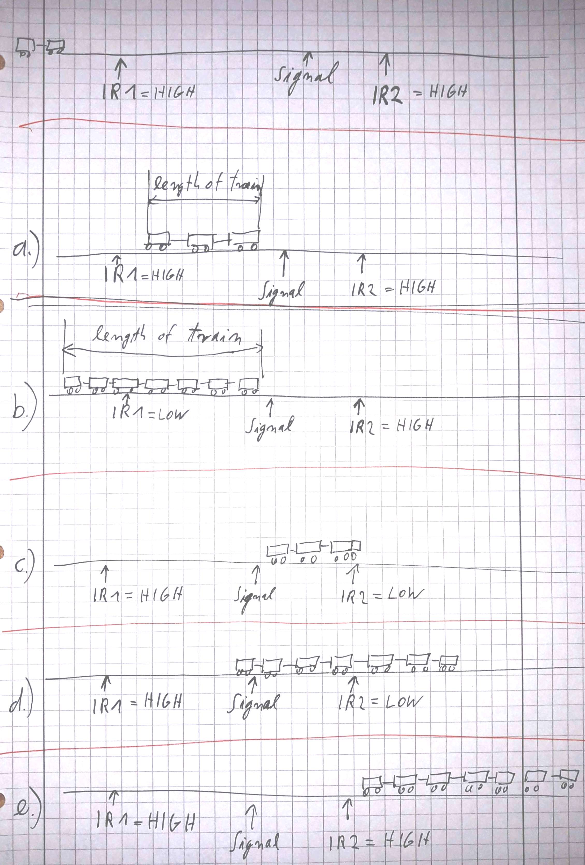
it is still not all clear to me. And for clarification a more detailed description is needed. I could do a rough estimation you mean it this or that way and still could be wrong with the coded solution. It might be that there are different cases throgh different lengths of the train which might cause de-railing if a bad combination of factors occur.
I guess your last description posted while I was writing my post clears up most of it.
From reading this I'm even more convinced that a statemachine is the way to go
And all these things have to be considered for a good and reliable working solution.
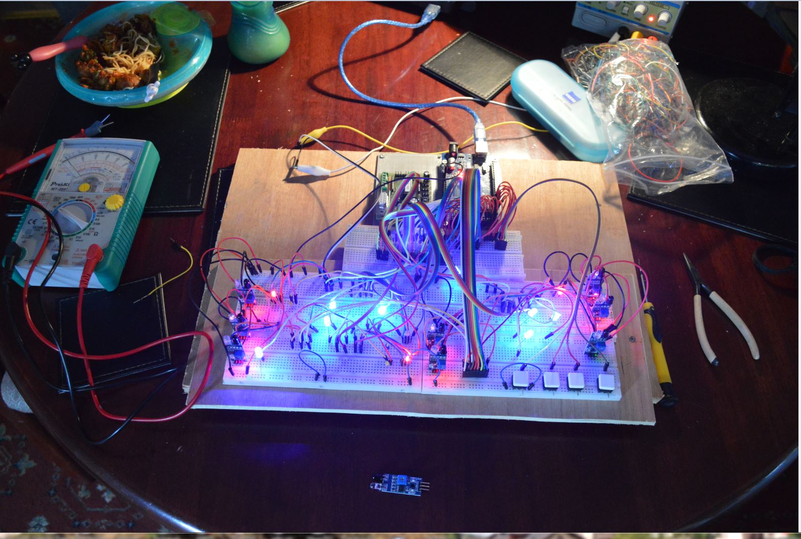
I have made a rough drawing that shows my understanding of your project. Please look at this drawing if my understanding is correct. If not make a similar drawing that shows how it really is. This drawing shall give you an example of how things can be cleared up by a "quick and dirty" hand-drawing. Only the principles have to be recognisable.
The basic principle is
1.) to analyse which sensor has witch state (LOW or HIGH) in which situation
2.) is there a fixed sequence of sensor-state-changes (IR1 goes from HIGH to LOW and stays LOW until ... etc. etc. etc.)
This may afford more drawings than I have done so far if there are a lot of variables like different train-lengths, etc.
Most users here would shout a "Hooray! finally a single user that posts sufficient hand drawn pictures of all states that could happen Very interesting combination of factors very intriguing challenge to write the code to solve this control-problem!"
If my understanding of the situation is 80% correct a statemachine will fulfill all your dreams how to control it. And once you have understood the basic principle of statemachines you can write code that everybody drops the jaw on the floor about what wild things go on on your modelrailway precise as a clockwork never crashing anything.
So give it a try to draw a corrected picture. And give it a try to understand how statemachines work.
If your situation is clear to us other users we will support you to get it going.
best regards Stefan
any newbee can apply the most professional habit from the first line of code they write on their own:
add only ONE thing at a time. Test/debug that ONE thing until that ONE thing works reliable - repeat.
The sad thing is: only the REAL professionals write code this way.