I'm trying to build an infrared tripwire to detect when a HO scale model train passes, using this module:
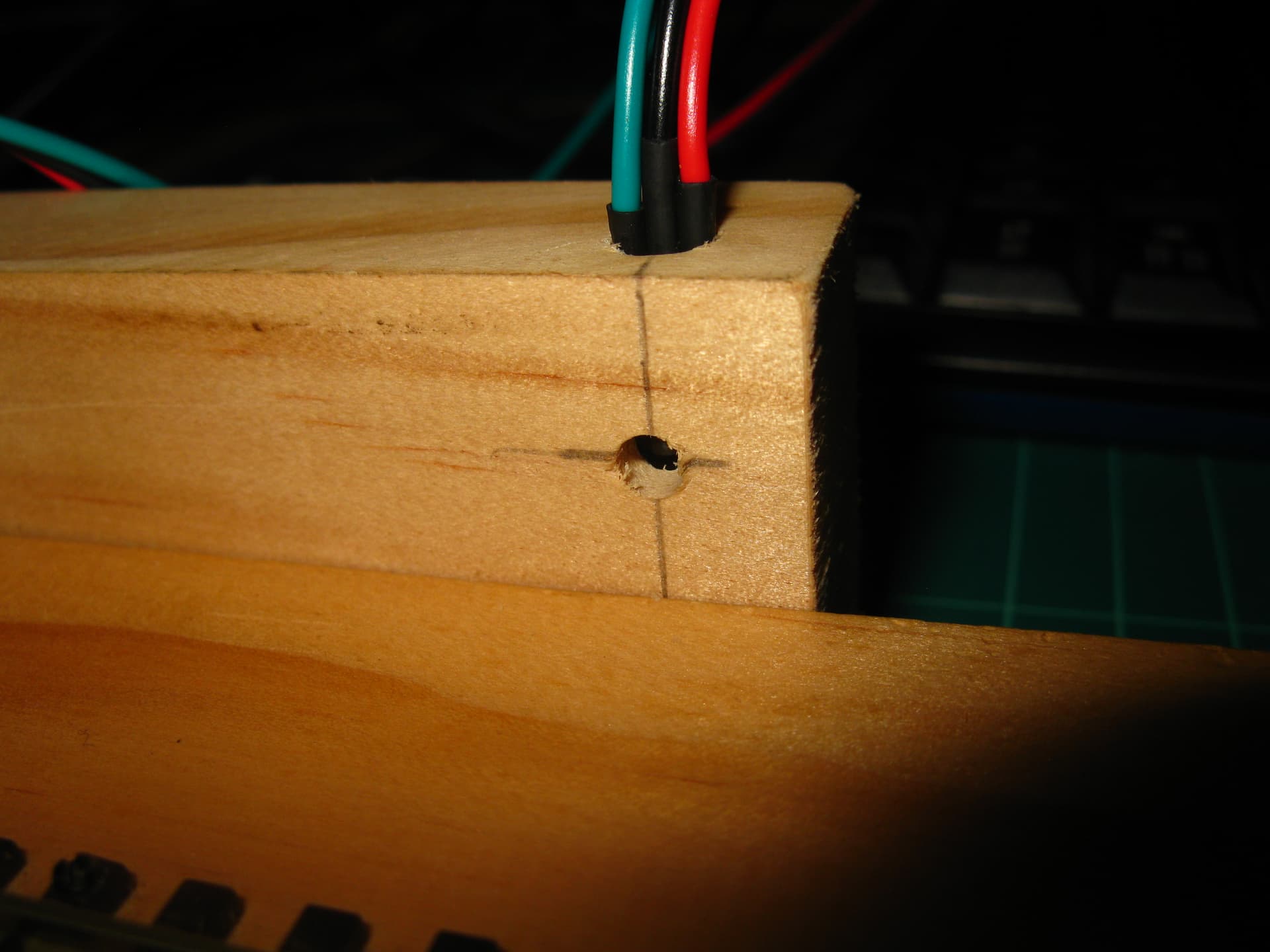
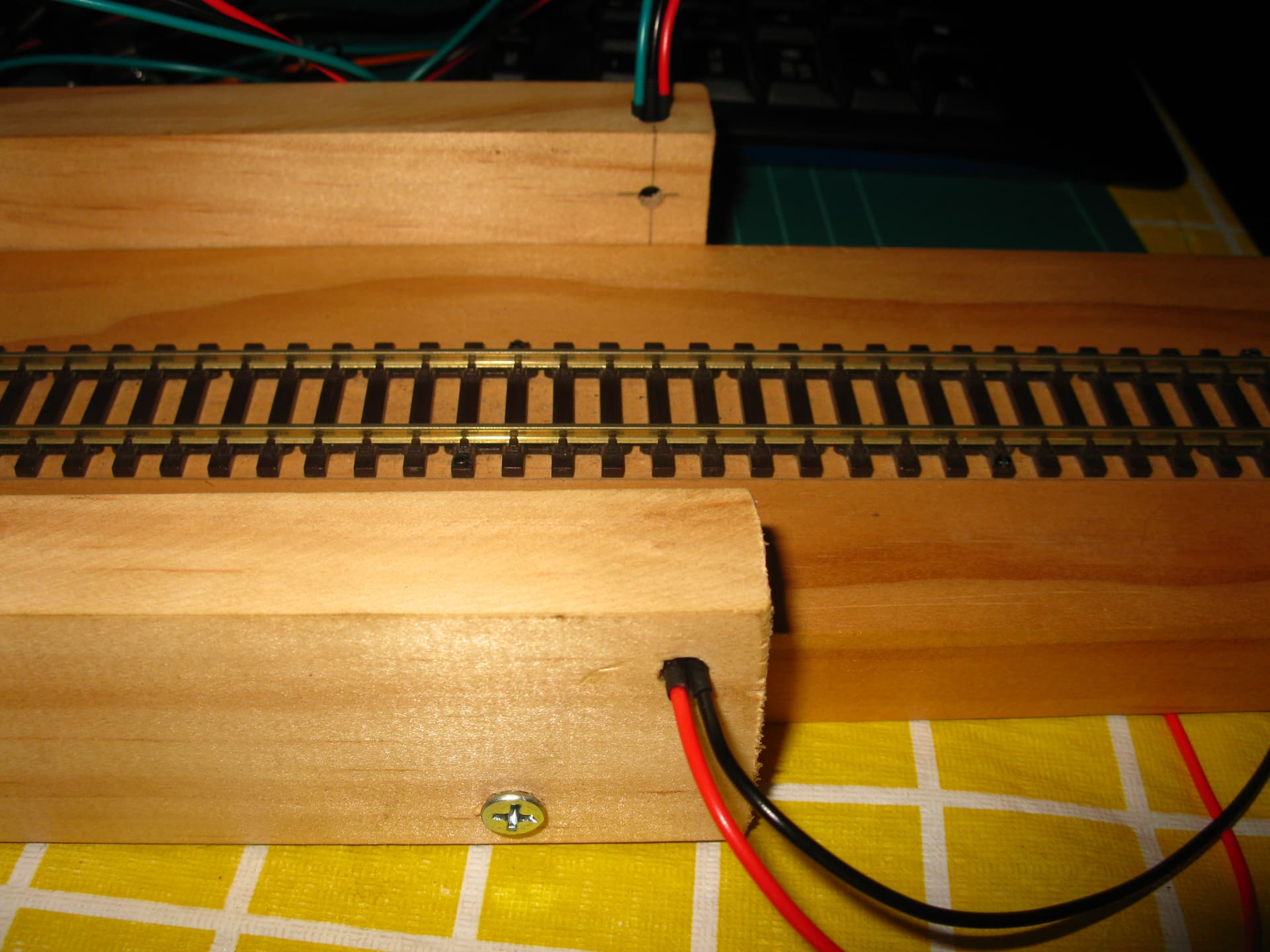
I have de-soldered the transmitter led and the three pin receiver, and re soldered them to leads. Then I have placed each part (transmitter led and receiver) on separate sides of the track. Last night, I tested the output pin of the module and it always outputs ~0.5 volts, whether the IR led is on or off. I have made sure that the led is focused directly on the receiver, but that doesn't change anything. It doesn't work. It does not detect whether a train or anything else has passed through the beam.
This is my code:
[code]
#include "U8glib.h"

U8GLIB_ST7920_128X64_4X u8g(10);

uint8_t draw_state = 0;

#define SENSOR_DISTANCE  200000 // [um] measured distance between the two IR beams
#define INIT_TRAIN_LENGTH    20 // [cm] New measurement only starts when train fully passed
// Loco Length can be changed via keyboard input
#define SENSOR_L_PIN 6
#define SENSOR_R_PIN 7

byte l_r, state;
byte scale, scale_old;
byte units, units_old = 99; // 0=MPH, 1=km/hr, 99=startup dummy
int train_length, serialread;
unsigned long start_us, stop_us, measured_us, waittime;
float m_per_s;
float km_per_hr;
float mi_per_hr;

void read_write_scale() {
  if (Serial.available()) {
    serialread = Serial.parseInt();
    if (serialread) train_length == serialread;
    Serial.print(F("Train length set to: "));
    Serial.print(train_length);
    Serial.println(F(" cm"));
    Serial.println(F("Waiting for train ..."));
    Serial.println();
  }
  scale = 87;                        // scale HO
  if (!digitalRead(14)) scale = 45;  // scale O
  if (!digitalRead(15)) scale = 76;  // scale OO
  if (!digitalRead(16)) scale = 120; // scale TT
  if (!digitalRead(17)) scale = 160; // scale N
  if (scale != scale_old ) {
    scale_old = scale;
    Serial.print(F("Scale set to: 1/"));
    Serial.println(scale);
  }
  units = digitalRead(8); // 0=MPH, 1=km/hr
  if (units != units_old ) {
    units_old = units;
    Serial.print(F("Units set to: "));
    if (units) Serial.println(F("km/hr"));
    else      Serial.println(F("MPH"));
    Serial.println(F("Waiting for train..."));
  }
}

void setup() {
  pinMode(13, OUTPUT);
  pinMode(SENSOR_L_PIN, INPUT_PULLUP);
  pinMode(SENSOR_R_PIN, INPUT_PULLUP);
  pinMode( 8, INPUT_PULLUP);
  pinMode(14, INPUT_PULLUP);
  pinMode(15, INPUT_PULLUP);
  pinMode(16, INPUT_PULLUP);
  pinMode(17, INPUT_PULLUP);
  pinMode(18, INPUT_PULLUP);
  Serial.begin(9600);
  train_length = INIT_TRAIN_LENGTH; // [cm]
  Serial.println();
  Serial.print(F("Train length is set to "));
  Serial.print(train_length);
  Serial.println(F(" cm "));
  Serial.println(F("For longer trains change this by typing"));
  Serial.println(F("in the input field above and hit ENTER"));
  //  Serial.println(F("For auto measurement with Traincontroller:"));
  //  Serial.println(F("1: Open TC Speed Profiling Tab"));
  //  Serial.println(F("2: Start AutoHotKey"));
  Serial.println();
  read_write_scale();
  digitalWrite(13, HIGH); // LED on means ready for measurement
}

void loop() {
  read_write_scale();

  switch (state) {
    case 0: // initial state, ready to start measuring
      if (digitalRead(SENSOR_L_PIN)) {
        start_us = micros();
        l_r = 0;
        state = 1;
      }
      if (digitalRead(SENSOR_R_PIN)) {
        start_us = micros();
        l_r = 1;
        state = 1;
      }
      break;

    case 1: // wait for the other sensor to be triggered
      digitalWrite(13, LOW);
      if (!l_r) {
        Serial.println(F("L >>> R"));
        while (!digitalRead(SENSOR_R_PIN)) {} // loop here until sensor R is triggered
      }
      else {
        Serial.println(F("L <<< R"));
        while (!digitalRead(SENSOR_L_PIN)) {} // loop here until sensor L is triggered
      }
      stop_us = micros();
      state = 2;
      break;

    case 2: // calculate and show speed values
      measured_us = stop_us - start_us - 10UL; // -10 to compensate for code delay
      m_per_s = float(scale) * float(SENSOR_DISTANCE) / float(measured_us);
      km_per_hr = 3.6 * m_per_s;
      mi_per_hr = 2.23694 * m_per_s;
      if (!units) {
        Serial.print(mi_per_hr);
        Serial.println(F(" MPH"));
      }
      else        {
        Serial.print(km_per_hr);
        Serial.println(F(" km/hr"));
      }
      Serial.println();
      waittime = (int)(10UL * measured_us * (unsigned long)train_length / (unsigned long)SENSOR_DISTANCE + 1000UL); // [ms]
      // measured_us is needed for a move of SENSOR_DISTANCE um
      // measured_us * train_length / SENSOR_DISTANCE) time is needed for train_length to pass
      Serial.print(F("Wait "));
      Serial.print(waittime);
      Serial.println(F(" ms"));
      // delay(waittime);
      digitalWrite(13, HIGH); //Next measurement can start when LED is on
      Serial.println(F("Waiting for train..."));
      state = 0;
      break;
  }
}
[/code]
The code and basic idea for this project come from an online tutorial: