I hope you're all doing well. I'm working on a circuit to control the intensity of a load using PWM, and I'd appreciate your feedback to help me understand an issue I'm facing.
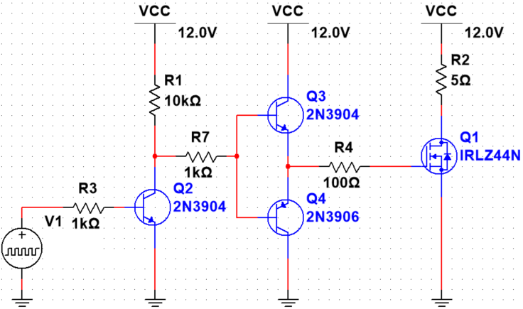
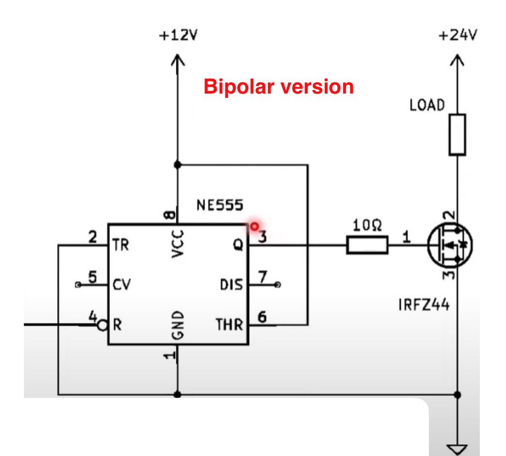
The PWM signal comes from a microcontroller at 3.3V, and I'm using a 2N3904 transistor to shift the signal up to 12V. After that, I added a push-pull stage to "clean up" or sharpen the square wave that drives the gate of an IRFZ44N MOSFET.
The circuit looks simple, but I’ve noticed the MOSFET heats up significantly during operation. Is this kind of heating normal due to switching losses? Interestingly, when I drive the MOSFET gate directly with 12V (without the push-pull stage), it seems to heat up less.
My eventual goal is to add feedback using a shunt resistor, since I already have an analog circuit that performs this type of control and I’d like to migrate it to a digital version to improve efficiency. However, if the MOSFET isn’t being driven correctly, I can’t move forward with the control loop.
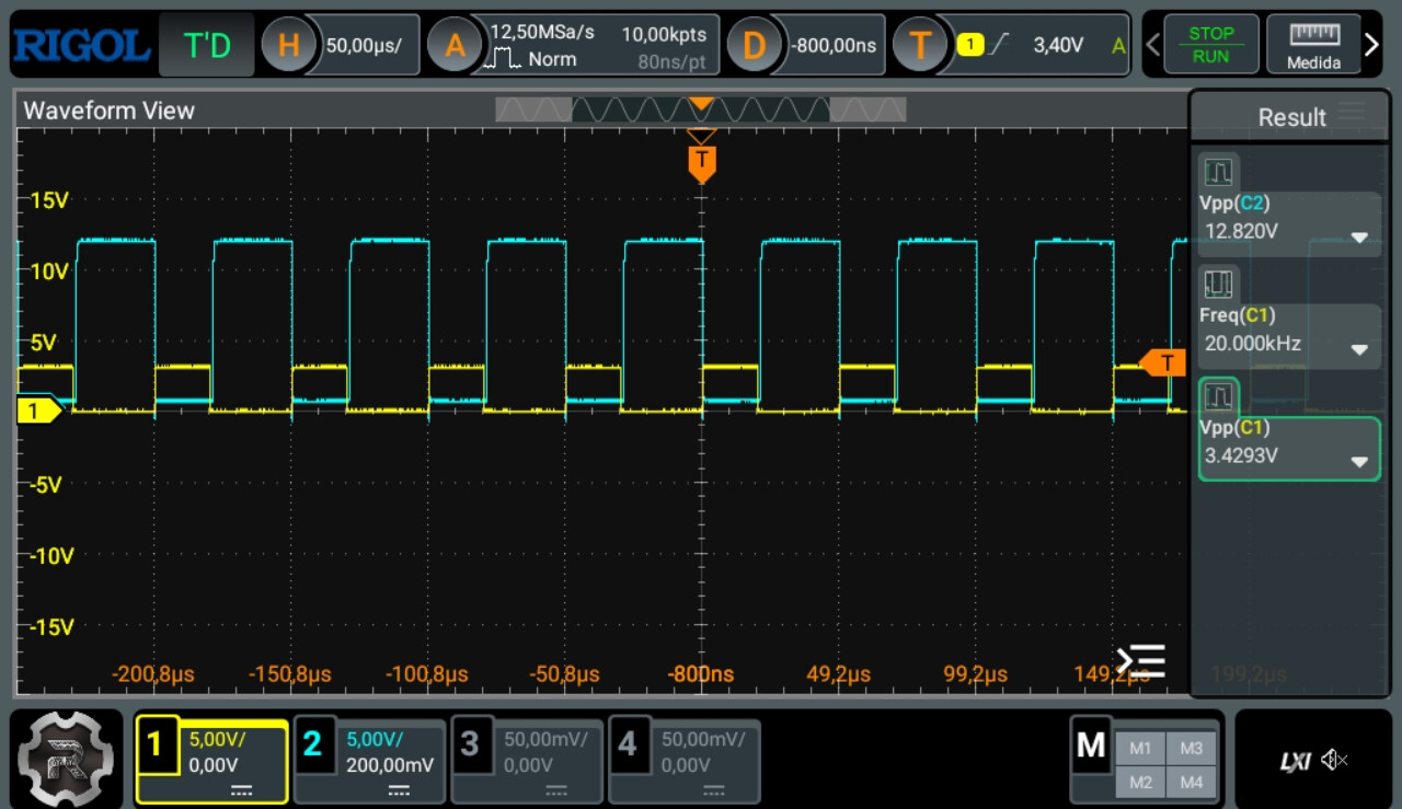
I've attached oscilloscope screenshots showing the input and output PWM signals, as well as the schematic of the circuit I'm currently using.
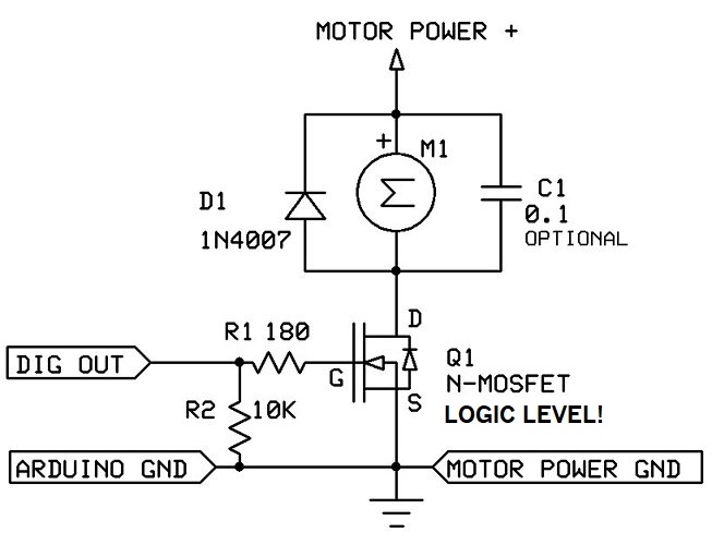
Use a logic level MOSFET instead, like the IRLZ44N, and drop the rest of the circuit.
You're right, the IRLZ44N is definitely better suited for low logic levels like 3.3V or 5V. However, if I use the IRFZ44N and adapt the PWM signal to 12V, there shouldn't be any problem, right?
Sure, but since you say that the MOSFET is heating up, there is a problem. What that might be is not clear from the scope traces, as it isn't clear which points in the circuit are monitored.
I suspect that your MOSFET driver design (which is not the best) doesn't match what was actually built and tested. Look at some other driver design examples.
isn't clear which points in the circuit are monitored.
The yellow signal is the PWM output from the microcontroller, and the blue signal is the PWM signal on MOSFET gate.
MOSFET driver design (which is not the best) doesn't match what was actually built and tested.
I’m curious about your comment that the driver design is “not the best.” I stepped up the signal and added a push-pull stage, which I thought was a proper approach—most of the circuits I’ve seen online follow a similar structure.
Of course, I might be missing something important, so I’d really appreciate your input.
How would you improve it?
Well if the MOSFET was fully on (100% PWM) then it would only generate about 100mW of heat.
Power = I²R = 2.4²*18mΩ
So if it is getting HOT it must be due to switching losses. However your signals look like they do have fast rise and fall times. Look at the drain signal.
There are many problems with the posted schematic, primary among them the value of R4.
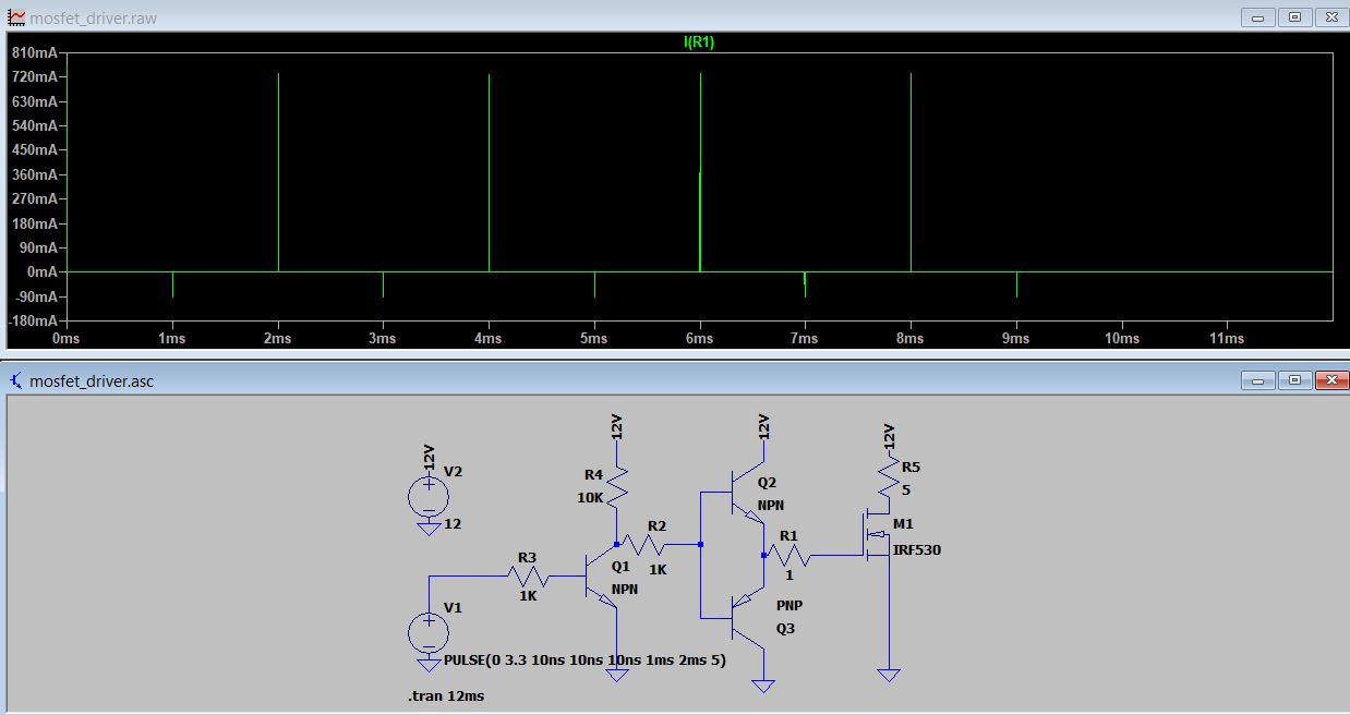
This is a quick simulation of the circuit with a much lower value of R4 (R1 in the figure below, which is not supported by the choice of small signal transistors for Q3 and Q4):
Scope trace is the gate current. Note the asymmetry.
Thanks for the simulation and explanation! I understand now that driving the gate directly or with only a 1 Ω resistor would indeed switch the MOSFET very fast—but at the cost of multi‑ampere current spikes, extreme EMI, and likely overloading my small signal transistors.
I would use a MOSFET driver IC.
Based on your experience, which gate driver would you recommend for controlling the MOSFET in this case? (I will use change the mosfet to IRLZ44N)
Also, would I connect the PWM signal directly to the driver input, or should I keep part of my original circuit (like the transistors) in between?
I'm not exactly sure what you mean.
My PWM signal is running at 20 kHz. I used that frequency just because I found it in an example online, not for any specific reason.
At this point, I don't have a fixed application for the circuit. I'm building it more as a general purpose driver to control things like motors, LEDs, etc.
Would you recommend a different frequency for better performance?
I guess you did not understand what I said in post #10
Frequency is not the issue, rise and fall times are.
Your suspicion about switching losses would make sense if the gate rise and fall times were very slow but looking at the scope traces they appear to be very fast.
So it isn't heating because of switching losses, it must be IR losses.
Did you look at the drain signal
Thanks a lot! I see that these gate drivers work like high current logic buffers, almost like AND gates but designed to drive MOSFETs.
I’d just like to clarify one thing:
Do I need to provide a PWM signal of at least 5 V directly to the driver’s input, and then connect the output straight to the MOSFET gate—with no resistor in between?
In my case, the PWM signal comes from a microcontroller running at 3.3 V.
Since the datasheet says the driver operates from 4.5 V to 18 V, I guess I’d need to keep my first transistor stage just to level-shift the PWM up to 5 V or 12 V for the driver input. Is that right?
I drove the gate drivers with 3V3 directly from a microcontroller running on 3V3, a PIC PIC32MX170F256B if you are interested. For power to the gate drviers I used 12V. Please read the datasheet for power requirements, there is a requirement for a 1μ0 and a 0μ1 capacitor close to the power pin.
If you look at the electrical specifications on page 3 you will see the logic 1 input high voltage minimum is 2V4, so 3V3 is fine.
Note also the 2 inputs to each driver and that they feed logic gates, be sure to tie any unused inputs low or high as appropriate, do not leave them floating.
While I agree with that to a point Jim I think you also have to take frequency into account because each transition from high to low or low to high is an event where losses take place, more transitions, more time for heating, more heat. So I would suggest that it's true that rise times are really important, but higher frequency also means more heating.
@ingyou my use was for LED lighting control and runs at (from memory) about 700Hz, which is sufficient for my needs. No significant heating from my MOSFETs, even at several amps.
Well, I'm not generalizing, as I have been trying to point out the rise and fall times appear to be very fast so I don't think that changing the frequency (within reason) is going to have a big impact on switching losses.
Something else is wrong with the circuit or testing
I'm not sure if you're referring to the rise and fall times.
With the oscilloscope probe on the drain and no load connected, I get a fall time of 114 ns and a rise time of 285 ns. With a load, the fall time increases to 200 ns (but it fluctuates a lot), and the rise time decreases to 25 ns.
I also tried lowering the switching frequency to 10 kHz, and in that case, the MOSFET didn’t heat up as much, so it seems like frequency also plays an important role.
I might be saying something that doesn’t make much sense, but that’s because my knowledge of electronics is still limited. I'm doing my best to learn.
The 25ns should not cause switching losses and even the 200n fall is less than 0.5% of the signal period, so I can't see how your MOSFET is getting hot.
When you say "hot" if you mean hot to where it will burn, then something else is wrong.
If you connect 12v to the gate with the 5 ohm load does it get "hot"?