Hi. I should start by warning that I am a complete noob when it comes to anything regarding mechatronics or coding and it all seems like witchcraft so I apologise in advance for asking stupid questions.
The project I'm trying to figure out involves having a conveyor belt mounted to load cells to measure the weight of the product moving along it, an adjustable rotary dial with a display and a small pump powered by a stepper motor. This pump would apply a liquid to the product on the conveyor belt and would sometimes be for example 150ml/100kg or it might be 400ml/100kg depending on the job.
My question is, can an Arduino take the Mv from the load cells and multiply that number by whatever the rotary dial is set to (depending on how many ml/100kg the job requires) and output a voltage to the stepper motor to control it? And if so, what else is required? Does the reading from the load cell need to be amplified for the Arduino to recognise it? Does there need to be a potentiometer added in somewhere?
If it can be done I'll start a new topic in the "Jobs and paid consultancy" part of the forum but just trying to figure out if I'm even on the right track first.
This link is for the pump I'm using.
This link is for the load cells. https://www.ausweigh.com.au/Latest/Loadcells/AL6N.aspx
The rotary dial/display is a ZK-SMC02. I have these already but I'm definitely open to suggestion if there's a better/more suitable option.
Cheers.
This does not seem out of reach but You need a bit more specification on how you proceed.
Are you pouring the liquid as the belt moves or calculating how much of a product ended up in a bin at the end of the conveyor belt and pouring the liquid there? Ot Is it just a point or a portion of the belt that gets the liquid as the product passes under the spray point?
Managing Time, conveyor belt speed, distance from drop point to spray point and integration will be part of your maths
is this application to run 24/7?
what is environment? e.g. in an industrial application use solderable or screw type breakout boards or even a custom PCB
also good quality power supplies
if you use the dial to set the pump would you require some indication of the setting, e.g. on an LCD display - maybe worth using a rotary encoder rather than a potentiometer
would you require remote monitoring/control, e.g. via Bluetooth from a smartphone or via WiFi to a web page on a PC?
Hey thanks for the reply. Good guesses but no. It’s actually for applying insecticide and fungicide to grain and pulses that will be used as seed.
It would be a continuous process so no need to calculate batch sizing or anything. The belt is completely supported by 3 load cells and is only about 1800mm long from where the grain lands on the belt to where it falls off. When the grain falls off the end of the belt, the chemical would be added as it goes into a mixing auger.
The arduino would need to do a calculation of volts from load cells✖️number from rotary dial➗X to get a 0-5V or 0-10V that runs the pump motor.
To work out what X is I would have to figure out how many tons/hr is moving across the belt and measure the volts coming out of the load cells to get a baseline number. Then work out how many ml/min the pump is moving at a certain voltage.
Different chemicals have different application rates ranging from 80ml/100kg up to 400ml/100kg. Do you have any recommendations for what should be used to tell the arduiono what rate it needs to be applying? I’m not sure what l should even be googling unfortunately.
I still feel you miss some important data if the process in continuous. 80ml/100kg is an instant value if you have 100kg and you mix. but if there is a flow...
for example How long does the grain stays within the mixing auger and how does it get out?
do you keep dumping grain in the auger whilst you mix?
is the flow out of the auger similar to the conveyor flow ?
I could see a converter belt filling up a mixing auger calculating weight and then chemical being added and mixed and then the auger would be emptied. Whilst the mixing happens the conveyor could be either stopped or routed to a second auger to be filled and if timing is matching when the second auger is full and ready for the chemical mix, route the conveyor back to the first auger which will have been emptied in some way
otherwise the mixing should be done whilst the grain keeps moving along a different conveyor at the same speed to not block the flow
If You are running a serious business using commersial grade of equipment is advised. Suppose some disturbance adds way too much of spray, what will the consequencies be?
The use of pesticides is usually surrounded by rules and regulations and mistakes can be costly.
The auger will take the grain away as fast as the belt is feeding it in so there's no pause in the process. I have a similar belt setup currently that is just used for weighing product. It takes the weight every 3.5 seconds and adds it to the total because this is how long it takes to get from one end of the belt to the other.
If I have a throughput of say 30,000kg/hour and I want to apply 80ml/100kg this means I need the pump to do 400ml/min. If the pump happens to need 3V to move at 400ml/min and the load cell happens to put out 12mV when there is 30,000kg/hour moving across it, the calculation that the arduino would have to perform is (12X80)/320=3V to the pump. If the product moving across the belt reduced to 15,000kg/hour and the mV therefor dropped to 6mV the calculation would then be (6x80)/320=1.5V Then if I had to increase the rate to 200ml/100kg, the new calculation at 15,000kg/hour would be (6x200)/320=3.75V
These numbers are all hypothetical and I don't actually know what the output from the load cells are likely to be until I add an amplifier and measure the volts at a certain kg/hour rate.
Sorry if this still doesn't make sense. Its very likely I'm still missing something. I assume it would be slightly move complicated than that calculation because it would have to take into account that the conveyor belt has a mass even when its empty so it will never be 0mV even when it's empty.
Absolutely. Using commercial grade equipment would be a must. The load cells and the pump I'm using are what I would really prefer to use as I have experience with them but everything else is up for debate. I have a very competent electrician that can wire everything up and do the fitout but he doesn't have a lot of experience with coding etc.
The setup You describe using Arduino stuff is everything but commersial grade. No safety related equipment can use it.
It's none of my business but how widely will the sprayed grains be spread?
The project itself is interesting but what is the really large picture?
As already told, apply a load cell amplifier, start with an empty conveyer and get the tara. A calibration run is needed to get scale factors.
Seems you have what you need if everything can be get in a flow and the mixing is correct just with a spray as the grain passes through the auger.
You need to weight the empty system and do a few dry runs to account for vibrations and you need to calibrate precisely your pump too. Quality power supply will be needed too.
This is doable but as an industrial process I would be concerned with risk management and would turn to pros to add all the necessary bells and whistles
Equipment for use with grain movement is likely to need ATEX certification to be legal ( or whatever your locality demands), due to the danger from dust clouds .
You need to check that first , as it may not be possible to build your own equipment for this and only assemble from approved parts, or via IS barriers - but you need to be competent to design with these .
No its not for any type of school project. Its just to try and make my job easier by automating parts of it. Considering your profile says your from Ballarat though, you've possibly come across similar things since there are some big businesses there that build/supply grain handling equipment.
I'll eat my breadboard if there aren't! Your electrician may be familiar with the requirements. An electrical engineer certainly would be.
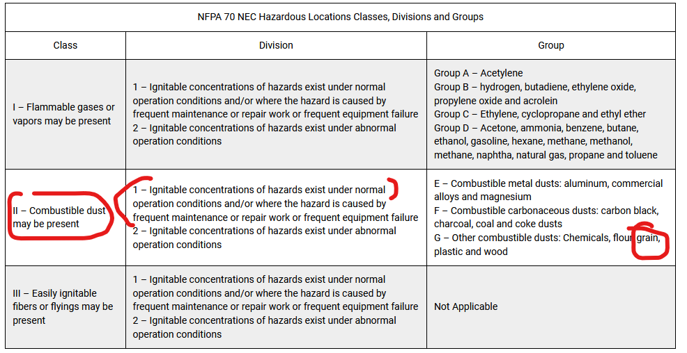
@hammy linked to UK info. FWIW, in the US, the classification system is as shown below. In Class II Div 1, for example, electrical equipment must be intrinsically safe or dust-ignition proofed by dust-tight enclosures or pressurizing the enclosures. Intrinsically safe equipment will be identified as such by the manufacturer. The "IP" system identifies dust-proof-ness.
Australia no doubt has similar requirements that must be followed and, as @hammy noted, pertinent regulations may also require a "competent person" to design systems for use in classified areas.
Ahh. I understand now. I thought hammy was referring to the actual machinery rather than the electrical components. No doubt there are all sorts of regulations regarding all that side of it. Anything electrical I've had built before for this type of thing has been in high IP rated cabinets etc.
I should point out I won't be doing any of this work myself and I'm mainly just trying to find out if what I want to do can be done and if so how. I've been hit by enough electric fences to know that electricity and I don't mix well. But hopefully I can read enough on here to get my head around it enough that when I talk to an automation guru about doing the job, I don't sound like a complete idiot.