Back-in-my-day hard disc drive (for example, HP7906 - weighing 50kg! with 10MB per removable platter!) heads were aligned against a "servo" platter and "servo head," the "servo platter" being the defacto "measure from me" cylinder/track/sector other heads would be adjusted in/out/forward/backward. In my world, the definition of "servo(thing)" meant a reference... and the task used feedback measured from the servo heads and the heads being aligned.
The servo platter resides on the permanent, bottom disc of the HP7906 drive, behind the power switch (see time 2:15 of the video). The servo platter is the "under" side of the permanent disc, with the top side of the permanent disc user read/write.
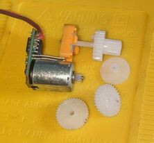
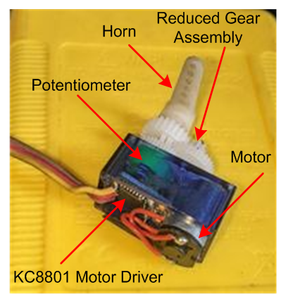
I have dismantled a newly purchased SG90 Servo (Fig-1) which contains two 8-pin SA8301 type Motor Driver chips. I am searching for English version data sheets of this chip as well schematic of the SG90 Servo System og Fig-1.
This is a Servo System of which the tiny DC Motor is a component. The yellow part is the 3-terminal potentionmeter which gets coupled with the Motor shaft via reduction gears.
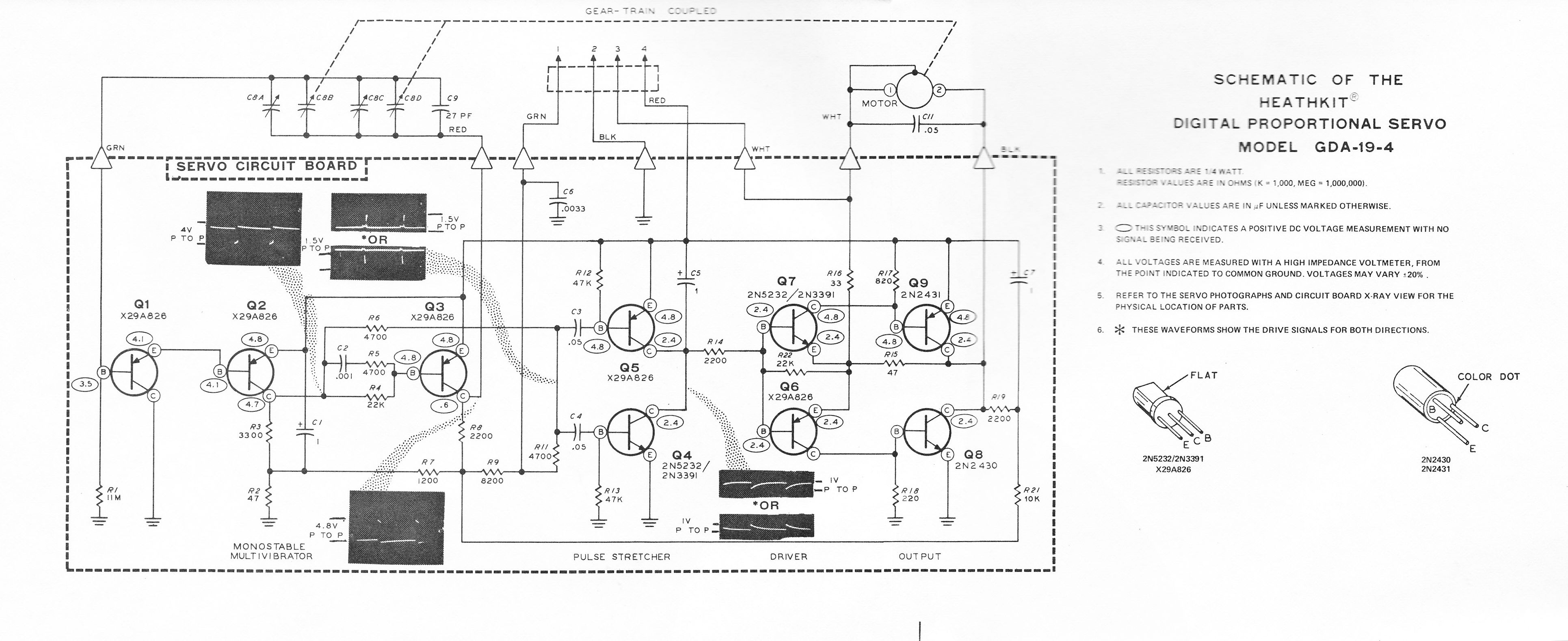
It might be helpful to find schematics of older servo motors, before China put all the active components on a single chip. I could swear I once read a datasheet/appnote on some low-number LMxxx chip that was very enlightening, ut I can't find anything now. (Hmm. Probably the NE554; but I don't see the app note.)
It's pretty simple, in principle. You compare the motor-coupled pot "current position' with the input "desired position" and drive an H-bridge one direction or the other, until the next input pulse comes in. A sort of 50Hz bi-directional PWM. I vaguely recall at least one design where the Pot was used to form pulses, and the "subtraction" of Pot Pulse vs Input Pulse gave you an H-bridge pulse width that was proportional in size to the delta, rather than just running full "on" in a direction for the entire 20ms. (It's a bit mind boggling that 50Hz is "fast enough" PWM for such applications, but it does more-or-less match up with the response time of typical hobby servo motors...)
I would think that the modern chips have a CPU in them.
In fact, it would probably be a very educational project to use an Arduino + motor driver + gear motor to implement a servo...
Not even a chip to decipher. I remember reading a technical article in a model airplane magazine that described a “pulse stretcher” circuit that took the difference between the pulse signal from the receiver and the pulse generated by the feedback pot of the servo to drive the motor in the proper direction. It was way over my high school age and knowledge to fully understand.
The text of the document I relied on AI to read for me mentions using a constant current source to feed into one of the capacitors to make a triangle wave for the generated pulses. Maybe with a constant current source, they can use a potentiometer an constant capacitance instead of a pair of variable capacitors?
In any case, it looks like the non-digital servos use analog circuits to generate a feedback signal to balance transistors driving opposite sides of the DC motor. The input control signal drives one leg, and the generated feedback signal drives the other.
I meant that I think it's well within the range of things that a fairly new Arduino programmer could accomplish (and feel accomplished about, having duplicated the functionality of a real product rather than some abstract principle.)
Pulsein(signal), analogRead(pot), digitalWrite(motorDirection)... Piece of cake!
(Furthermore, there's opportunity to expand on the basic principles. Another pulseIn instead of analogRead? Different types of sensors for current position? More remote sensor positions (720degree operation, anyone? Linear Servo?)
fancier algorithms (up to full PID?) for driving the motor? Soft endpoints? Magnetic actuators instead of motors? Etc.)
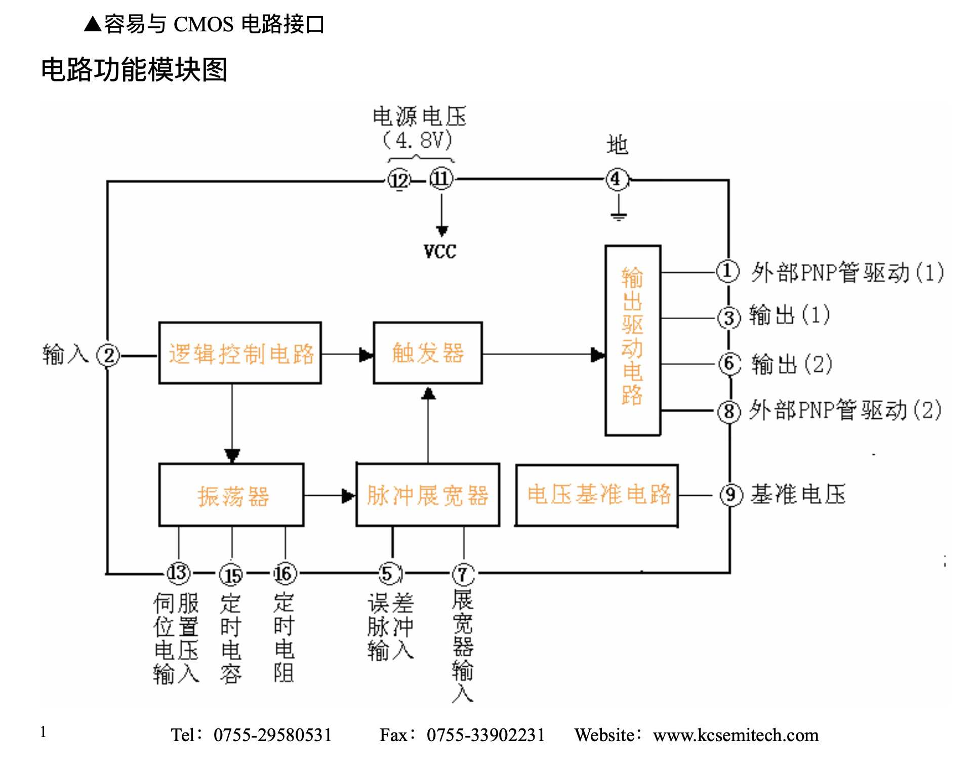
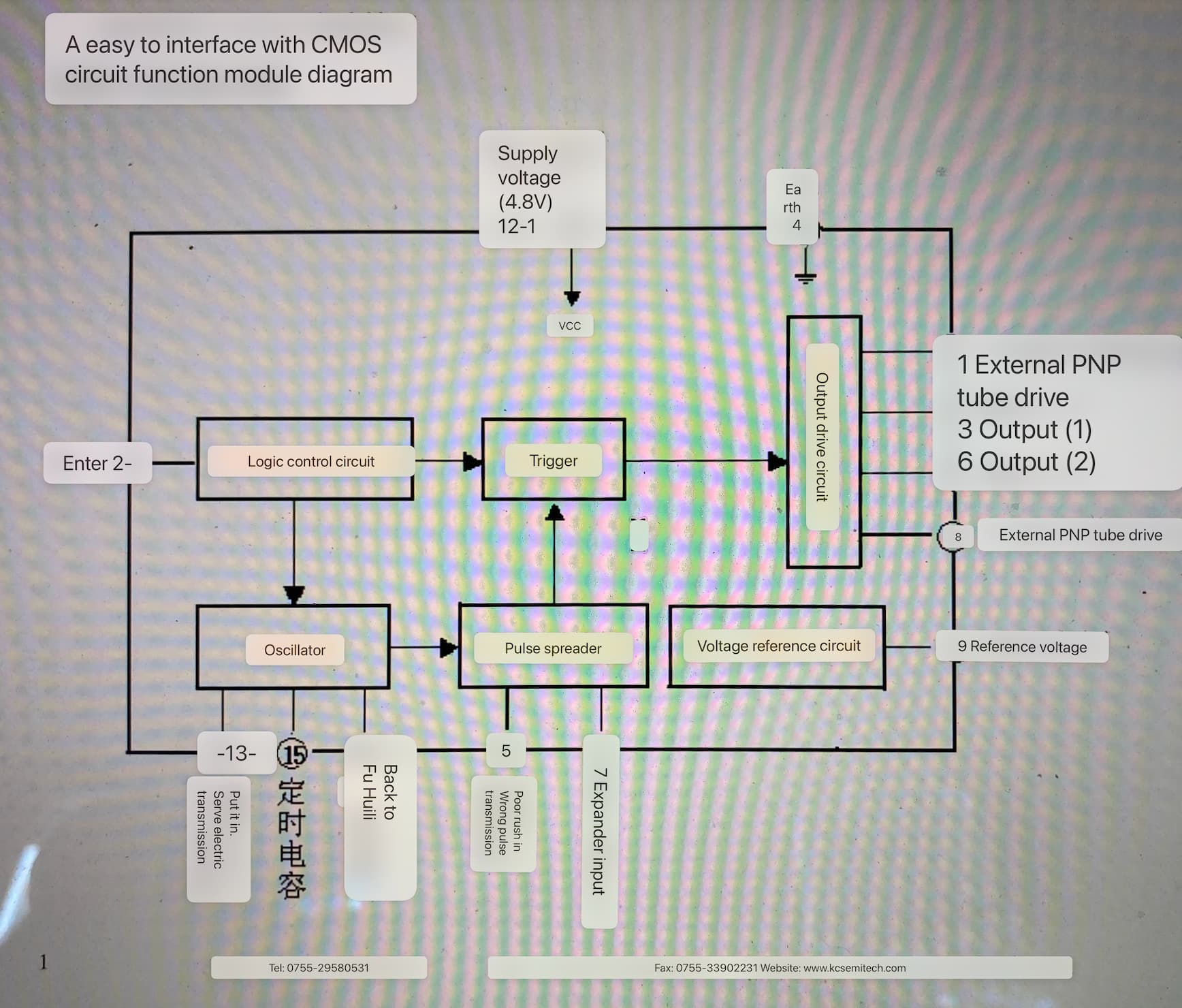
This is an impressive explanation of the working principle of a closed-loop system (the Servo System). It sheds light on the necessity of maintaining a 50 Hz PWM signal at the input of the KC8801/SA8301 controller of SG90.
Once, I studied the Servo System of a printer to understand how the positioning of the print head is achieved. There was a slotted disc mounted on the shaft of the DC Motor to receive feedback by interrupting the IR signal. The feedback signal was sent to the main board to compare it with the input signal in order to decide when to cut off the motor power.
In the case of the SG90, the potentiometer (coupled with the motor shaft) receives the feedback signal, which is not passed to the UNO; instead, it is processed by the built-in controller in conjunction with the PWM input to decide when to cut off the motor power.
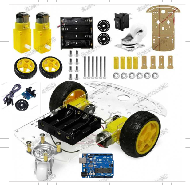
That's what I do with my pupil using the following components of a 3-wheel Hobby Robot Car to understnad the principles of Servo System.
I have found the following write-up online, which looks very in-line with SG90.
"The Servo itself also generates a set of pulses and uses the width of the received pulse as a reference to adjust its internal timer. It does this by using the error (defined as the difference between the 2 pulses) to drive a motor, which then turns a set of gears. As it does so a potentiometer is also moved by the gear train, altering the internal timer. When the pulse trains match (within a deadband) the servo stops moving. The Servo output horn is fixed to the end of this gear train. An update rate of 50Hz is fast enough for most purposes, but if driving servos from a microcontroller they are usually quite forgiving of faster (and slower update rates.) If you do not send any control pulses then the servo will hold its last position, or give up holding position altogether. This is another none specified feature that varies from manufacturer to manufacturer."
I am yaking abot the old days printers; where, there was slotted disc on the shaft of the DC Motor to receive feedback by interrupting IR signal coming from the device to be positioned. As it is receiveing feedback, it is a closed loop system; hence, it is a Servo System.
Maybe, maybe not.
IF the controller has a CPU, I'd expect it to "remember" the last input signal width.
What an old Analog Servo would do without an input signal is an interesting question!
I have performed some measurements on the disasembled SG90, and I have gathered the following data. The Servo has used KC8801 Motor Driver (Fig-1).
Figure-1:
Data:
Sn. Code          PWM        Motor Volt      Motor Volt     Angular
    Executed      Pulse      during Process  after Process  Position
1   s.write(180)  2.3 ms     +2.2V           ~0.00V         180 deg
2   s.write(0)    0.53 ms    -2.4V           ~0.00V         0 deg
3   s.write(60)   1.14 ms    +1.05V          ~0.00V         60 deg
4  ----------     disconnect  ---            ------         holds previous
                                                            position
The table above indicates that once the horn has reached the desired angular position, the motor driver cuts off power to the motor terminals by zeroing the width of the resultant PWM signal.
The 50 Hz control signal (input PWM from the UNO) remains active because the UNO has no feedback indicating whether the motor has reached the desired angular position. Transitioning from one angular position to another requires a certain amount of time during which the control signal must remain present. This allows the motor driver to compute the error signal, which will adjust the pulse width of the input PWM signal before applying it to the motor terminals.
Not strictly true…
Many use DC motors with encoder wheels to achieve speed and accuracy. Effectively ‘creating’ a servo to control and maintain the position of the motors.