Issue coding RTC 7 segment clock

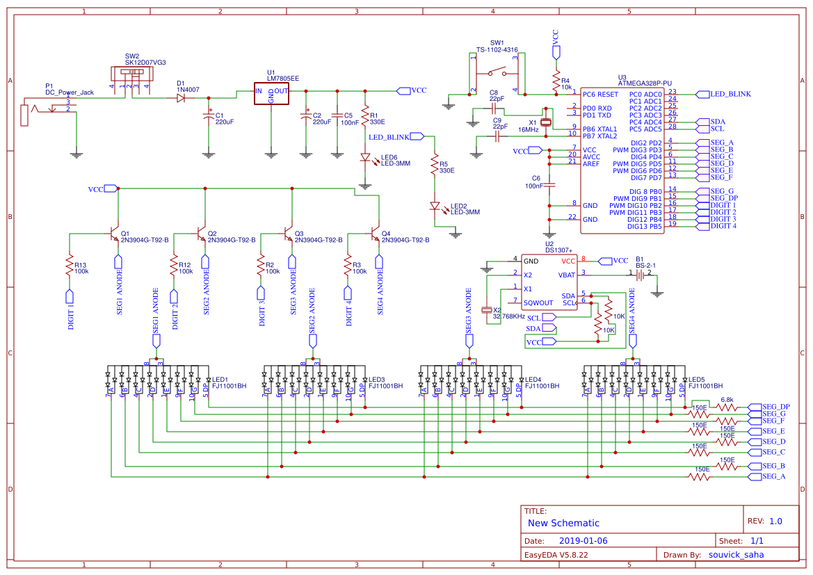
I made a custom PCB RTC 7 Segment display clock based on a project I found online.

The schematic of my project can be found here: Digital Clock.pdf | DocDroid

I used an Atmega32u4 for my project and I was able to get the code to work on my test led which was tied to pin 20 of the MCU, but the code that I used from the instructables project isn't exactly working. it uploads properly and everything, but doesn't display the time.

Here is the result of uploading the code:
IMG-6615

Here is the altered code:

#include <Wire.h>
#include "RTClib.h"

#define A 3
#define B 2
#define C 0
#define D 1
#define E LED_BUILTIN
#define F 4
#define G 12
#define DP 6

#define CA1 8
#define CA2 10
#define CA3 9
#define CA4 11

int d = 2, first_h=0, second_h=0, first_m=0, second_m=0, sec_old=0, h, m, s;
RTC_DS1307 rtc;

const int segs[7] = { A, B, C, D, E, F, G};

const byte numbers[11] = {0b1000000, 0b1111001, 0b0100100, 0b0110000, 0b0011001, 0b0010010,
0b0000010, 0b1111000, 0b0000000, 0b0010000};

void setup()
{
  
  Serial.begin(57600);
#ifdef AVR
  Wire.begin();
#else
  Wire1.begin();
#endif
  rtc.begin();
for(int i=2;i<=13;i++)
{
  pinMode(i, OUTPUT);
}
for(int i=2;i<=13;i++)
{
  digitalWrite(i, LOW);
}  
}

void loop()
{
  DateTime now = rtc.now();

  h = now.hour();
  m = now.minute();
  s = now.second();

  first_h = h / 10;
  second_h = h % 10;
  first_m = m / 10;
  second_m = m % 10;
  
  lightDigit1(numbers[first_h]);
  delay(d);
  lightDigit2(numbers[second_h]);
  delay(d);
  lightDigit3(numbers[first_m]);
  delay(d);
  lightDigit4(numbers[second_m]);
  delay(d);


} 

void lightDigit1(byte number) {
  digitalWrite(DP, HIGH);
  digitalWrite(CA1, HIGH);
  digitalWrite(CA2, LOW);
  digitalWrite(CA3, LOW);
  digitalWrite(CA4, LOW);
  lightSegments(number);
}

void lightDigit2(byte number) {
  digitalWrite(CA1, LOW);
  digitalWrite(CA2, HIGH);
  digitalWrite(CA3, LOW);
  digitalWrite(CA4, LOW);
  if(s % 2 == 0)
  digitalWrite(DP, LOW);
  else
  digitalWrite(DP, HIGH);
  lightSegments(number);
}

void lightDigit3(byte number) {
  digitalWrite(DP, HIGH);
  digitalWrite(CA1, LOW);
  digitalWrite(CA2, LOW);
  digitalWrite(CA3, HIGH);
  digitalWrite(CA4, LOW);
  lightSegments(number);
}

void lightDigit4(byte number) {
  digitalWrite(DP, HIGH);
  digitalWrite(CA1, LOW);
  digitalWrite(CA2, LOW);
  digitalWrite(CA3, LOW);
  digitalWrite(CA4, HIGH);
  lightSegments(number);
}

void lightSegments(byte number) {
  for (int i = 0; i < 7; i++) {
    int bit = bitRead(number, i);
    digitalWrite(segs[i], bit);
  }
}

It's preferable if you post the schematics as images here.

1 Like

Here's the schematic of the instructables project: https://content.instructables.com/F2O/RWID/JQWT42D7/F2ORWIDJQWT42D7.png
and the original instructables: https://www.instructables.com/DIY-Digital-Clock-With-7-Segment-LED-Display/.

For some reason the forum didn't allow me to post more than two links since I'm new here, sorry about that.

Segments E, F and G are on with A and B glowing. In what state is the code (running? not?) Have you looked underneath for a missing penny or bent pin(s)? Do I see two bent pins on U1?

Soldering doesn't look great on the ATMega chip... you sure everything is ok electrically ?

What exactly do you mean by what state is the code running? It uploads each time without errors but I can't tell if its something I soldered or the code. Which component is U1? are you referring to the MCU? The schematic I made the MCU is U20.

I tried using a soldering wick to remove the solder and redo it, should I check the continuity of each pin with a multimeter?

The schematic is for an ATmega328P. You can't use the same schematic for an ATmega32u4. I'm sure the Arduino pins map to different physical pins.

Yeah I saw that he used a different MCU, hence why I changed the segment pins mapped in the code, but it still doesn't seem to work.

States:

  1. Power, no code loaded, not running
  2. Power, code loaded, not running
  3. Power, code, running

U3 is what I should have written. Sorry. I assumed "U1" because there is only one "Ux" visible (to me)... and the "two bent pins" look like "two four lifted traces"

It would be in state 3, as the LEDs on the 7 segments are lighting up but not showing the time. I ran code as a test that supposed to count from 1 to 9 and all 8 segments light up but it didn't show most of the numbers properly other than number 2, which makes me think something is wrong with the software. The code I found here: https://srituhobby.com/how-does-a-7-segment-display-work-arduino-with-7-segment-display-step-by-step-instructions/
As for the lifted traces, I checked the continuity with a multimeter and the meter showed continuity, so presumably that shouldn't be an issue. The solder job was rather crappy, as I have trouble soldering MCUs.

Okay. This shows what pins are effected.

If you applied power to the board (no code running) and the segments in the photo (e, f and g) are lit, that would eliminate code from being wrong.

The 7segs are "a" at the top, going around clockwise through "f" then the center is "g" (with "h" as a decimal point). The "always lit" segments are e, f and g. The number 2 uses "e" and "g" of these three segments. That tells me that e, f, AND g are "forward biased" (+ on the anode, - on the cathode) without being told to by the running code. In "arduino" code, that would mean the "anode-connections" of e, f and g are "high" when they should not be.

I would look at "what drives (provides forward bias to) the segments.

1 Like

Are you certain you have the correct pin number for the E and F segments? On the Leonardo pinout PD4 is D4, PD5 is the TX LED.

In the schematic, the transistors driving the displays would turn on with a LOW output, your code looks to be using a HIGH output.

< edit >
The code in setup() to set the output mode for the pins also appears to be wrong, you are not usings pins 2 through 13.

1 Like

Maybe you need to step back, save your fancy clock code - and write a simple program tha turns on one segment at a time,

It will be about 15 lines long, and you can slow it down to check the pin states in real time with your meter, or a led & resistor.

1 Like

Vf on a GREEN display is 2.4V. The pn (and hence driver) is for a RED (1.7V) display. The project is shown running from 3V3. The drive transistor only has .7V across it, your design is marginal just on a superficial inspection. Since the pn is incorrect, it could be common anode vs common cathode too.
You DID prototype it with the FINAL components before production, yes?

1 Like

The segments don't turn on until the code is ran, all 4 segments are common anode displays, which is why I chose to use PNP transistors as opposed to NPN

I did some prototyping yes, but clearly not enough, I'm using common anode displays for all 4 but I'm guessing because of the green displays there isn't enough voltage for the project to work? I'm a little bit confused.

PD5 is pin 22 which connects to TXLED and PD4 is pin 25 which connects to digital pin 4, looking at my schematic and the atmega32u4 pinout that part seems fine. I see what you mean with the for loop in the setup, the reason the person who made the project did this was because they tied the pins A through G sequentially, so because of the way I made my board I can't exactly do this. I'm assuming then I can't use a for loop to turn on the segments at all, but rather write a pinmode for each one individually?

Guessing? You designed a PCB board and built it and you don't have a DMM to make a simple voltage measurement? See post #14. Also, aren't the segments illuminated in the photo you posted?

I'm assuming then I can't use a for loop to turn on the segments at all, but rather write a pinmode for each one individually?

You can if you put the pin numbers in an array.

1 Like

Right, the segments do turn on, I'll work on each segment individually and then I'll figure out how to get the time code to work through some modifications. I do have a DMM I could use to check the voltages as well.