Here you go
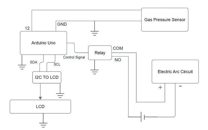
In this design, where does relay go ?
In my Post#17 schematic:-
You do not need a relays. It is replaced by the opto coupler.
In your Post#21 circuit:-
Why is there a box saying "I2C TO LCD"? A box indicates some sort of integrated circuit.
What voltage is supplied to the LCD? These are normally 3V3, but you can get 5V ones.
Why are there no pull up resistors on the SDA and SCL lines?
The ground symbols you use are normally used for the protective mains ground. The symbols I used are for the common signal ground.
What voltage is the battery driving the electric arc circuit?
You know all the answers to this because only you have your circuit. We can only know what you tell us, and so far there is a lot of information we don't know.
Hi, @umer-bit
How have you got the controller mounted?
Is it inside a grounded metal case, to shield it from interference.
Can you post some images of your project?
So we can see your component layout.
Thanks.. Tom.. ![]()
![]()
![]()
![]()
This box shows the I2c to LCD connection converter.
5 V
Two battery cells each of 1.46 V in series so total of 2.92 V as battery voltage.
Ok I tried the opto coupler but it didn't work, I did exactly like in your schematic but electric arc circuit did not activate when I gave High logic to input and other pin to ground paired with resistor. It just doesn't seem to work. I bought multiple PC817 ICs and all of them didn't work.
Actually the controller is far from the electric arc circuit and arduino runs perfectly even when sparking is occuring. However, whenever I place the electric arc power connection inside the relay (basically connecting it physically ), the resets would happen. Shielding is not helping here.
Time to build a test circuit just for the opto and use a DMM to see if it’s working.
Unless you got a box of cheap fakes, it seems unlikely that they are all bad.
I tested the opto alone, if I use an led at the output, it lights up and acts as intended but when i place the electric arc connections, it doesn't work. Does it has to do something with current consumption and limits of phototransistor.
Hi, @umer-bit
Can you post us a new schematic?
Can you post us a new image of your project?
Thanks.. Tom.. ![]()
![]()
![]()
![]()
Try changing the resistor input from 4K7 to 1K, and see if that does the trick.
did that still didn't work, I have uploaded my latest schematic again, could you please take a look and now suggest something ?
Hi,
Have you measured the voltage on the two arc circuit wires that you connect to the opto.
Measure without the opto connected.
Measure with the opto connected and the LED ON then OFF.
Check DC volts and AC volts between the wires.
How did you determine that these wires were the arc ON/OFF control?
Thanks.. Tom.. ![]()
![]()
![]()
![]()
2.86 V
LED on : 1.81 V
LED off : 2.87 V
Which wires ?
If you are talking electric arc ones, I literally touch the wires and they activate the electric arc circuit
What I think is that opto couplers would not work in my case. Electric arc circuit requires more current and output transistor cannot provide it.
However, I found something else i.e Solid state relay. I read that it is suitable for high current driven circuits.
I need your guys suggestion on this do you also see it as a potential solution or what ?

