I have a setup that uses an esp32, an I/O expander MCP23017 and an OLED. The MCP23017's I2C address is 0x27 and the OLED's is 0x3C. I am using the following libraries: MCP23017.h and SSD1306Wire.h. Everything worked perfect on the breadboard. However, when I ported the setup to a pcb, I have the following remarks during the testing:
Sometimes (in almost 10% of the tests ) the boot of the esp32 takes almost 1 minute to complete. It gets stuck in the MCP23017 initialization in the setup().
 for (int i = 0; i < numRows; i++) {
        mcp23017.pinMode(rows[i], OUTPUT);
    }
when this happens, the MCP23017 works randomly (I mean mcp23017.digitalWrite does not reliably control the pins as expected.)
the remaining 90% of the tests are fine: The boot of the esp32 is normal (no delay during initialization) and MCP23017 works perfect.
I added a 0.1uf ceramic condenser between the MCP23017's VCC and GND and the issue seemed to be solved. But, after intense testing, unfortunately, I found that the issue happens rarely in almost 2% of the tests.
Any advice is appreciated
Were the leads to this short? If they are through hole capacitors long leads can cause the capacitor's resonant frequency to be lowered making it less effective.
The best way is to use surface mounting capacitors. These can be soldered between adjacent tracks in strip board.
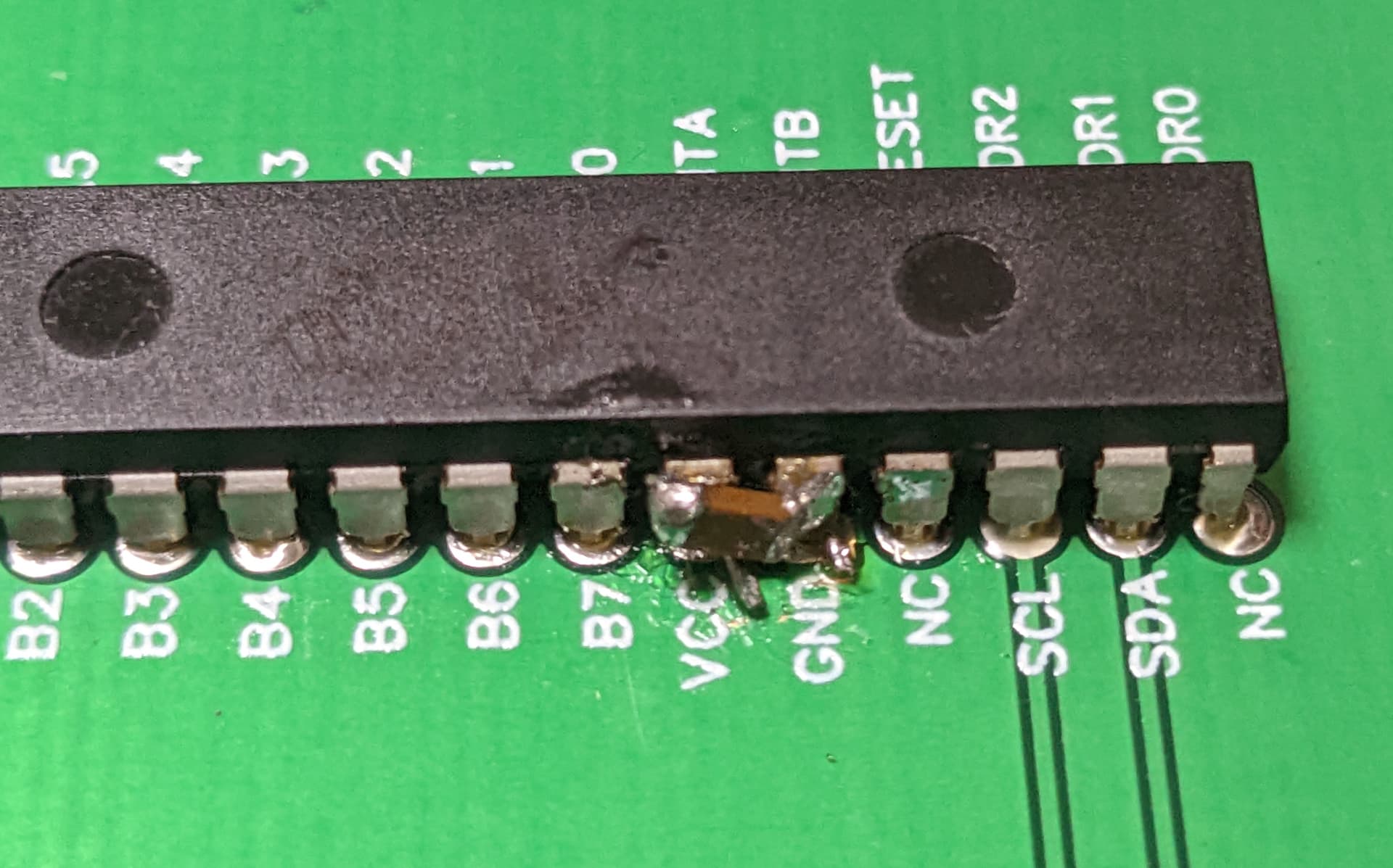
The issue was solved by soldering a 0.1uf SMD capacitor between VCC and GND of mcp23107 (see picture). I will correct the PCB design . Thanks a million for your help.
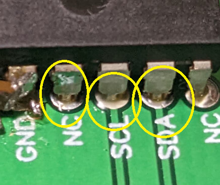
The image of your PCB shows that while it is soldered, it is not soldered very well. That is the soldered joint did not get hot enough. This might be due to the lack of power in your iron, or using lead free solder which needs to be hotter.
But the main problem might be that you are soldering pins that go straight to ground plane. This tends to suck all the heat out of your iron trying to heat up the ground plane, which by definition is quite a good heat sink.
There is a technique in laying out a PCB for getting round this, it is called "thermal relief". Search for images on this term, or / and see this link:-