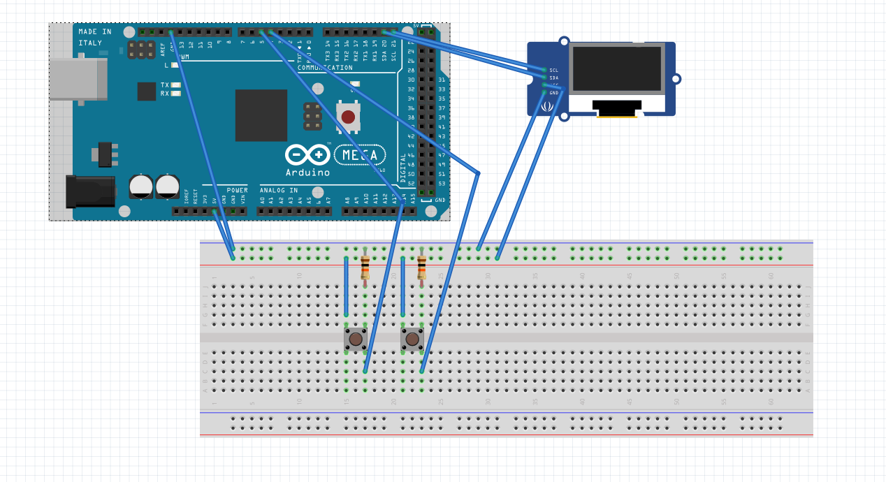
Hi, im trying to code a device that would help me count and time how quickly i produce garments at work, using 4 pushbuttons, a microprocessor (elegoo mega 2650 R3 for testing then esp12f once soldered) and an SH1106 oled screen.
Im running into an issue when trying to code a plus and minus button that increment and decrement a variable (garmCount) when pressed, the first pushbutton (plus) increments but the second pusbutton(minus) doesn't decrement.
both buttons are wired the same way, with a 10k pulldown resistor each to a common ground, but even if i move the breadboard wire from minus to plus it doesn't work. in some cases i've found that unplugging the wire for minus with decrement garmCount but im unsure what in my code would cause that issue
#include <Adafruit_SH1106.h>
#include <Wire.h>
#include <SPI.h>
#include <Adafruit_GFX.h>

#define OLED_RESET 4
Adafruit_SH1106 display(OLED_RESET);

//pin numbers for plus, minus, reset and mode buttons
const int buttonPlus = 4;
const int buttonMinus = 5;
//const int buttonRst = 6; //unused
//const int buttonMode = 7; //unused

//variables
int garmCount = 0;//integer for number of garments
//int timer = 0; //unused integer for timer

//button state variables for each button
int buttonPlusState = 0;
int lastButtonPlusState = 0;
int buttonMinusState = 0;
int lastButtonMinusState = 0;
int buttonRstState = 0;
int lastButtonRstState = 0;
int buttonModeState = 0;
int lastButtonModeState = 0;


void setup() {
  // put your setup code here, to run once:
//initialise all buttons as inputs
pinMode(buttonPlus, INPUT);
pinMode(buttonMinus, INPUT);
pinMode(buttonRst, INPUT);
pinMode(buttonMode, INPUT);


//initialise display
Serial.begin(9600);
display.begin(SH1106_SWITCHCAPVCC, 0x3C);

//show and clear buffer image, change when know how
display.display();
delay(2000);
display.clearDisplay();

//prep text formatting for use and show message to visually verify
display.setTextColor(WHITE);
display.setTextSize(1);
display.setCursor(0,0);
display.print("text test");
display.display();
delay(2000);
display.clearDisplay();//clear text
display.display();


}
//define garmCount function for easier counter printing
void garmCountDisplay() {
display.setTextColor(WHITE);
display.setTextSize(1);
display.setCursor(0,0);
display.print(garmCount);
display.display();

}

void loop() {
// read state of plus button
buttonPlusState = digitalRead(buttonPlus);

// compare plus button state to previous state, increment garm count if pressed
if (buttonPlusState != lastButtonPlusState) {
  if (buttonPlusState == HIGH) {
    garmCount++;
    display.clearDisplay();
    garmCountDisplay();
    }
    delay(50);//debounce
}
//update plus button state for next loop
lastButtonPlusState = buttonPlusState;

//read minus state
buttonMinusState = digitalRead(buttonMinus);

// compare minus button state to previous state, decrease garm count if pressed
if (buttonMinusState != lastButtonMinusState) {
  if (buttonMinusState == HIGH) {
    --garmCount;
    display.clearDisplay();
    garmCountDisplay();
    }
    delay(50);//debounce
}
//update minus button state for next loop
lastButtonMinusState = buttonMinusState;


}
I prefer the switch going to ground especially if long wires are involved. here is why:
Using a switch to ground (also called "active-low switching") for external switches is a common design practice in electronics. Here is the key reason:
Less Noise: Ground is typically a stable reference point, reducing the likelihood of false triggering from electrical noise compared to pulling a pin high with a switch.
If the wire to the switch gets disconnected or broken, the pull-up resistor ensures the input remains at a defined logic level (high). This prevents the input from floating, which could lead to unpredictable behavior.
If the wire to the switch gets disconnected or broken, the pull-up resistor ensures the input remains at a defined logic level (high). This prevents the input from floating, which could lead to unpredictable behavior.
i dont believe the issue is circuit based as if i take one button, wire it correctly, and connect to pin 4, the counter increments. if i then move the wire to pin 5 on the arduino, it doesnt decrement, which feel like a sign that it's a code issue.
i understand the concept behind the terminals for the switches, but no matter if i wire the button in either of these orientations, if signal wire is attached to pin 5 (or other pins, i troubleshot by defining it to 6 with the same issue) garmCount doesnt decrease
found the issue, after reseating everything one more time i found some weak connectors on the breadboard especially the rails , i must've just picked weak points every time i changed anything : |
im planning on using keyboard switches when i make up the final version to hopefully avoid fighting 4 pin buttons again