Hi there,
Tlc5948.h
#ifndef TLC5948_LIB_H
#define TLC5948_LIB_H
#include <SPI.h>

// pin assignments; todo replace with enum maybe
#ifdef ARDUINO_TEENSY41 // Teensy version
#warning "Using Teensy Pin Definitions"
#error "Unimplemented"
int const LAT = 0;   // latch control
int const GSCLK = 0; // pwm clock
int const SSEL = 0; // slave select, HW SS
int const SIN = 0;   // serial data input (to Tlc5948)
int const SOUT = 0;  // serial data output (from Tlc5948)
int const SCLK = 0;  // serial data clock
#else // assume Arduino Nano
#warning "Using Arduino Nano Pin Definitions"
int const LAT = 3;   // latch control, using D3
int const GSCLK = 9; // pwm clock, using D9 w/Fast PWM (~8Mhz)
int const SSEL = 10; // slave select, HW SS, not needed
int const SIN = 11;   // serial data input (to Tlc5948) HW MOSI, using D11
int const SOUT = 12;  // serial data output (from Tlc5948)  HW MISO, using D12
int const SCLK = 13;  // HW SCLK, using D13
#endif // ifdef ARDUINO_TEENSY41

// SPI settings
uint32_t const SPI_SPEED = 10000; // 10Khz to start //33000000; // 33mhz listed on data sheet
const unsigned int BIT_ORDER = MSBFIRST;
const unsigned int SPI_MODE = SPI_MODE0; // todo check if this is right
const int NUM_CHANNELS = 16;
const int PWM_FREQ = 490; // default arduino pin 9 freq

// led open, led short, output leakage, iref short flag, pre-thermal warning, thermal error flag
// SidFlags = BADPARSE TEF PTW ISF OLD LSD LOD
enum class SidFlags { NONE=0,LOD=1,LSD=2,OLD=4,ISF=8,PTW=16,TEF=32,BADPARSE=64 };

inline SidFlags operator|(SidFlags a, SidFlags b) {
    return static_cast<SidFlags>(static_cast<int>(a) | static_cast<int>(b));
}
inline SidFlags operator&(SidFlags a, SidFlags b) {
    return static_cast<SidFlags>(static_cast<int>(a) & static_cast<int>(b));
}
inline void operator&=(SidFlags& a, SidFlags b) {
    a = static_cast<SidFlags>(static_cast<int>(a) & static_cast<int>(b));
}
inline void operator|=(SidFlags& a, SidFlags b) {
    a = static_cast<SidFlags>(static_cast<int>(a) | static_cast<int>(b));
}
inline SidFlags operator~(SidFlags a) {
    return static_cast<SidFlags>(~static_cast<int>(a));
}

enum class Channels : uint16_t { // Channel masks
    none =     0x0000,
    chan_set = 0x0001,
    out0 =     0x0001,
    out1 =     0x0002,
    out2 =     0x0004,
    out3 =     0x0008,
    out4 =     0x0010,
    out5 =     0x0020,
    out6 =     0x0040,
    out7 =     0x0080,
    out8 =     0x0100,
    out9 =     0x0200,
    out10 =    0x0400,
    out11 =    0x0800,
    out12 =    0x1000,
    out13 =    0x2000,
    out14 =    0x4000,
    out15 =    0x8000,
    even =     0xaaaa,
    odd =      0x5555,
    all =      0xffff,
    upper8 =   0xff00,
    lower8 =   0x00ff,
};

inline Channels operator|(Channels a, Channels b) {
    return static_cast<Channels>(static_cast<int>(a) | static_cast<int>(b));
}
inline Channels operator&(Channels a, Channels b) {
    return static_cast<Channels>(static_cast<int>(a) & static_cast<int>(b));
}
inline void operator&=(Channels& a, Channels b) {
    a = static_cast<Channels>(static_cast<int>(a) & static_cast<int>(b));
}
inline void operator|=(Channels& a, Channels b) {
    a = static_cast<Channels>(static_cast<int>(a) | static_cast<int>(b));
}
inline Channels operator~(Channels a) {
    return static_cast<Channels>(~static_cast<int>(a));
}
inline Channels operator>>(Channels a, int b) {
    return static_cast<Channels>(static_cast<int>(a) >> b);
}
inline Channels operator<<(Channels a, int b) {
    return static_cast<Channels>(static_cast<int>(a) << b);
}
inline void operator>>=(Channels& a, int b) {
    a = static_cast<Channels>(static_cast<int>(a) >> b);
}
inline void operator<<=(Channels& a, int b) {
    a = static_cast<Channels>(static_cast<int>(a) << b);
}

enum class Fctrls : uint32_t { // function control masks and values
    blank_mask =      0x00001, // turns off outputs
    dsprpt_mask =     0x00002, // auto display repeat, DC,BC,GS data updated async
    tmgrst_mask =     0x00004, // allows LAT to control timing (new data interrupts)
    espwm_mask =      0x00008,
    lodvlt_mask =     0x00030,
    lsdvlt_mask =     0x000c0,
    lattmg_mask =     0x00300,
    idmena_mask =     0x00400,
    idmrpt_mask =     0x00800,
    idmcur_mask =     0x03000,
    oldena_mask =     0x04000,
    psmode_mask =     0x38000,

    psmode_none =       0x00000,
    psmode_sclk =       0x08000,
    psmode_data =       0x10000,
    psmode_noclk =      0x20000,
    oldena_mode_0 =     0x00000,
    oldena_mode_1 =     0x04000,
    idmcur_mode_2ua =   0x00000,
    idmcur_mode_10ua =  0x01000,
    idmcur_mode_20ua =  0x02000,
    idmcur_mode_1ma =   0x03000,
    idmrpt_mode_0=      0x00000,
    idmrpt_mode_1=      0x00800,
    idmena_mode_0=      0x00000,
    idmena_mode_1=      0x00400,
    lattmg_mode_17 =    0x00000,
    lattmg_mode_33 =    0x00100,
    lattmg_mode_65 =    0x00200,
    lattmg_mode_129 =   0x00300,
    lsdvlt_mode_035 =   0x00000,
    lsdvlt_mode_045 =   0x00040,
    lsdvlt_mode_055 =   0x00080,
    lsdvlt_mode_065 =   0x000c0,
    lodvlt_mode_03v =   0x00000,
    lodvlt_mode_06v =   0x00010,
    lodvlt_mode_09v =   0x00020,
    lodvlt_mode_12v =   0x00030,
    espwm_mode_0  =     0x00000,
    espwm_mode_1  =     0x00008,
    tmgrst_mode_0  =    0x00000,
    tmgrst_mode_1  =    0x00004,
    dsprpt_mode_0 =     0x00000,
    dsprpt_mode_1 =     0x00002,
    blank_mode_0 =      0x00000,
    blank_mode_1 =      0x00001,

    empty_bits   =      0x00000,
    full_bits    =      0xfffff,
};

inline Fctrls operator|(Fctrls a, Fctrls b) {
    return static_cast<Fctrls>(static_cast<int>(a) | static_cast<int>(b));
}
inline Fctrls operator&(Fctrls a, Fctrls b) {
    return static_cast<Fctrls>(static_cast<int>(a) & static_cast<int>(b));
}
inline void operator|=(Fctrls& a, Fctrls b) {
    a = static_cast<Fctrls>(static_cast<int>(a) | static_cast<int>(b));
}
inline void operator&=(Fctrls& a, Fctrls b) {
    a = static_cast<Fctrls>(static_cast<int>(a) & static_cast<int>(b));
}
inline Fctrls operator~(Fctrls a) {
    return static_cast<Fctrls>(~static_cast<int>(a));
}

enum class DataKind { gsdata, controldata, none };

class Tlc5948 {
    public:
        void updateDcData(Channels,uint8_t);
        void updateBcData(uint8_t);
        void updateGsData(Channels,uint16_t);
        uint8_t pushGsData(uint16_t);
        void updateFctrlData(Fctrls);

        void exchangeData(DataKind);
        SidFlags getSidData(Channels&,Channels&,Channels&,bool = false);
        void startGsclk();
        void stopGsclk();
        void pulseLatch();
        Fctrls getFctrlBits();
        void printGsDataBuf();
        void printSpiBuf();
        void printCtrlDataBuf();
        void begin(void);

        Tlc5948();

    private:
        SidFlags sidStatus;
        Fctrls funcControlBits;
        uint8_t gsDataBuf[32];
        uint8_t ctrlDataBuf[32];
        uint8_t spiBuf[32];

};

inline void pulse_high(int pinNum) { // ___----___
    digitalWrite(pinNum,HIGH);
    asm volatile ("nop"); // NOP*4 -> 1/16Mhz * 4 = 62.5ns * 4 = 250ns
    asm volatile ("nop");
    asm volatile ("nop");
    asm volatile ("nop");
    digitalWrite(pinNum,LOW);
}

inline void pulse_low(int pinNum) { // ---____---
    digitalWrite(pinNum,LOW);
    asm volatile ("nop");
    asm volatile ("nop");
    asm volatile ("nop");
    asm volatile ("nop");
    digitalWrite(pinNum,HIGH);
}

inline void notifyGsData() {
    digitalWrite(SIN,LOW); // GS data MSB is low
    pulse_high(SCLK); // __-__
}

inline void notifyControlData() {
    digitalWrite(SIN,HIGH); // Control data MSB is high
    pulse_high(SCLK); // __-__
    digitalWrite(SIN,LOW);
}

inline void Tlc5948::startGsclk() {
    // On Arduino Nano
    // timer 0 -> A: 6 B: 5
    // timer 1 -> A: 9 B: 10 * using this timer
    // timer 2 -> A: 3 B: 11

    // From https://withinspecifications.30ohm.com/2014/02/20/Fast-PWM-on-AtMega328/
    // and atmega328p datasheet

    // To set appropriate mode for PWM we need three settings enabled:
    // TCCRXA - PWM mode + output CLEAR invert/non-invert
    // Fast Pwm Mode(counts up and resets to 0, and changes output on OCR0X val)
    // \- We do this by settings WGM0[1:0] in TCCR0A to 1 and WGM02 TCCR0B to 1
    // \- WGM02 in TCCR0B also specifies that reset to 0 happens at OCR0A value
    // \- and not at TOP (255 for timer 0, 65536 for timer 1)
    // set COM0X1 bits to 1
    // \- sets output to clear on match and start from BOTTOM (non-inverting)
    ICR1 = 1; // according to datasheet this works well for static duty as TOP
              // using 1 as TOP gives 1 bit resolution but 8Mhz max frequency

    // enable A and B, using OCR1A TOP
    //TCCRXA = _BV(COM1A1) | _BV(COM1B1) | _BV(WGM11) | _BV(WGM10);
    //enable just A, using ICR1 as TOP (leave WGM10 as 0)
    TCCR1A = _BV(COM1A1) | _BV(WGM11);

    // TCCRXB - Timer control Reg b
    // controls: clock prescaler (and upper bits of WGM)
    // for timer0: CS0[2:0] = 001 -> prescaler = 1 (CLK is now 16Mhz)
    //       note: WGM02   =  1 -> set Fast PWM mode
    TCCR1B =  _BV(WGM13) | _BV(WGM12) | _BV(CS10);

    OCR1A = 0;

}

inline void Tlc5948::stopGsclk() {
    TCCR1A &= ~(_BV(COM1A1)); // disconnect A
}

inline void Tlc5948::pulseLatch() {
    pulse_high(LAT);
}

inline void Tlc5948::printGsDataBuf() {
    for (int i = 0; i < 32; i++) {
        Serial.print("0x");
        Serial.print(gsDataBuf[i],HEX);
        Serial.print(" ");
    }
    Serial.println();
}

inline void Tlc5948::printSpiBuf() {
    for (int i = 0; i < 32; i++) {
        Serial.print("0x");
        Serial.print(spiBuf[i],HEX);
        Serial.print(" ");
    }
    Serial.println();
}

inline void Tlc5948::printCtrlDataBuf() {
    for (int i = 0; i < 32; i++) {
        Serial.print("0x");
        Serial.print(ctrlDataBuf[i],HEX);
        Serial.print(" ");
    }
    Serial.println();
}

inline Fctrls Tlc5948::getFctrlBits() {
    return funcControlBits;
}
#endif
Tlc5948.cpp
#include "Tlc5948.h"

Tlc5948::Tlc5948() {
    sidStatus = SidFlags::NONE;
    funcControlBits = Fctrls::empty_bits;
    for (int i = 0; i < 32; i++) {
        gsDataBuf[i] = 0;
        ctrlDataBuf[i] = 0;
    }
}

// dot correction data, 7 bits per channel, 0 to 100%
void Tlc5948::updateDcData(Channels channelMask, uint8_t value) {
    value &= 0x7f;
    for (int i = 0; i <= NUM_CHANNELS; i++) {
        if ((channelMask & Channels::chan_set) != Channels::chan_set) { // write only to selected channels
            channelMask >>= 1;
            continue;
        }
        // writing 7 bits!
        int bitnum= i * 7;
        int bytenum= 31 - bitnum / 8; // offset from end of the array
        int align = bitnum % 8;
        ctrlDataBuf[bytenum] &= ~(0x7f << align) & 0xff;
        ctrlDataBuf[bytenum] |= (value << align) & 0xff;
        if (9 - align < 8) {
            ctrlDataBuf[bytenum-1] &= ~(0x7f >> (8-align)) & 0xff;
            ctrlDataBuf[bytenum-1] |= (value >> (8-align)) & 0xff;
        }

        channelMask >>= 1;
    }
}

// Global brightness control data, 7 bits for all Channels (25% to 100%)
void Tlc5948::updateBcData(uint8_t value) {
    value &= 0x7f;
    int endOfDcData = 31-NUM_CHANNELS * 7 / 8;
    ctrlDataBuf[endOfDcData] = value;
}

// Function Control, 18 bits
void Tlc5948::updateFctrlData(Fctrls f) {
    funcControlBits = f; // save this for easier modification
    unsigned long fbits = static_cast<unsigned long>(funcControlBits);
    int endOfDcData = 31-NUM_CHANNELS * 7 / 8;
    ctrlDataBuf[endOfDcData] &= ~(0xff << 7); // clear first bit value
    ctrlDataBuf[endOfDcData] |= fbits << 7; // first bit gets put atop bc data (7 bits)
    ctrlDataBuf[endOfDcData-1] = (fbits >> 1) & 0xff; // next 7 bits
    ctrlDataBuf[endOfDcData-2] = (fbits >> 9) & 0xff; // ...
    ctrlDataBuf[endOfDcData-3] = (fbits >> 17) & 0x01; // last 3 bits

}

// greyscale, pwm data, 16 bits per channel
// when blank bit of gs control reg is set (1), output is all 0's
// blank is set to 1 on startup, must write gs data before setting blank to 0
void Tlc5948::updateGsData(Channels channelMask, uint16_t value) {
    for (int i = NUM_CHANNELS-1; i >= 0; i--) {
        if ((channelMask & Channels::out0) != Channels::out0) {
            channelMask >>= 1;
            continue;
        }
        gsDataBuf[i*2+1] = value & 0xFF;
        gsDataBuf[i*2] = (value >> 8) & 0xFF;
        channelMask >>= 1;
    }
}

inline void copyBuf(void* inBuf, void* outBuf, unsigned int size) {
    uint8_t* inByteBuf = static_cast<uint8_t*>(inBuf);
    uint8_t* outByteBuf = static_cast<uint8_t*>(outBuf);
    for (unsigned int i = 0; i < size; i++) {
        outByteBuf[i] = inByteBuf[i];
    }
}

// send data from either ctrl buff or gs data buff
void Tlc5948::exchangeData(DataKind type) {
    SPI.beginTransaction(SPISettings(SPI_SPEED,BIT_ORDER,SPI_MODE));
    switch (type) {
        case DataKind::gsdata:
            copyBuf(gsDataBuf,spiBuf,32);
            digitalWrite(SIN,LOW);
            pulse_high(SCLK);
            break;
        case DataKind::controldata:
            copyBuf(ctrlDataBuf,spiBuf,32);
            digitalWrite(SIN,HIGH);
            pulse_high(SCLK);
            digitalWrite(SIN,LOW);
            break;
        default:
            break;
    }
    SPI.transfer(spiBuf,32);
    SPI.endTransaction();
    asm volatile("nop"); // give it a rest before we pulse high
    asm volatile("nop");
    asm volatile("nop");
    asm volatile("nop");
    pulseLatch(); // latch in the new data
}

SidFlags Tlc5948::getSidData(Channels& old, Channels& lsd, Channels& lod, bool refreshData) {
    if (refreshData) {
        exchangeData(DataKind::gsdata); // re-push in gsdata, pulling SidData out into spiBuf
        int delayMs = 0;
        Fctrls lattmg_bits = funcControlBits & (Fctrls::lattmg_mask);
        switch(lattmg_bits) {
            case Fctrls::lattmg_mode_17:
                delayMs = 17/PWM_FREQ*1000+1;
                break;
            case Fctrls::lattmg_mode_33:
                delayMs = 33/PWM_FREQ*1000+1;
                break;
            case Fctrls::lattmg_mode_65:
                delayMs = 64/PWM_FREQ*1000+1;
                break;
            default:
            case Fctrls::lattmg_mode_129:
                delayMs = 129/PWM_FREQ*1000+1;
                break;
        }
        delay(delayMs);
    }

    SidFlags flags = SidFlags::NONE;
    old = Channels::none;
    lsd = Channels::none;
    lod = Channels::none;

    for (int i = 1; i < 15; i += 2) { // every other byte is reserved, so just skip 'em
        uint16_t word = static_cast<uint16_t>(spiBuf[i]); // convert byte to 16 bit word so we can shift it
        if (word == 0) // skip empty words
            continue;
        switch(i) {
            case 13: // Misc bits
                if ((word >> 5) & 0x1)
                    flags |= SidFlags::ISF; // IREF is shorted
                if ((word >> 6) & 0x1)
                    flags |= SidFlags::PTW; // Pre-thermal warning
                if ((word >> 7) & 0x1)
                    flags |= SidFlags::TEF; // Thermal error flag
                break;
            case 11: // OLD bits 0..7
                old |= static_cast<Channels>(word);
                flags |= SidFlags::OLD; // Output leakage detected
                break;
            case 9: // OLD bits 8..15
                old |= static_cast<Channels>(word << 8);
                flags |= SidFlags::OLD; // Output leakage detected
                break;
            case 7: // LSD bits 0..7
                lsd |= static_cast<Channels>(word);
                flags |= SidFlags::LSD; // LED short detected
                break;
            case 5: // LSD bits 8..15
                lsd |= static_cast<Channels>(word << 8);
                flags |= SidFlags::LSD; // LED short detected
                break;
            case 3: // LOD bits 0..7
                lod |= static_cast<Channels>(word);
                flags |= SidFlags::LOD; // LED open detected
                break;
            case 1: // LOD bits 8..15
                lod |= static_cast<Channels>(word << 8);
                flags |= SidFlags::LOD; // LED open detected
                break;
            default:
                break;
        }
    }
    return flags;
}

void Tlc5948::begin() {
    // Note: driver must first send gs + dc/bc/fctrl data before it will turn on
    // this function just gets the buffers ready, 2+ calls to exchangeData are needed
    // to actually start the chip


    // pin assignments
    pinMode(SSEL,OUTPUT); // slave select output -> prevent SPI slave mode
    pinMode(SIN,OUTPUT); // MOSI -> data to TLC5948
    pinMode(SOUT,INPUT);  // MISO -> data from TLC5948
    pinMode(SCLK,OUTPUT);  // SCLK -> SPI clk
    pinMode(LAT,OUTPUT);   // latch control
    pinMode(GSCLK,OUTPUT); // PWM clock

    updateGsData(Channels::all,0xFFFF); // 100% brightness
    updateDcData(Channels::all,0x7f); // all dot correction to 100%
    updateBcData(0x7f); // global brightness to max

    Fctrls funcControls =   Fctrls::blank_mode_0    | // blank is set to 1 by chip, need to zero it out to use chip
                            Fctrls::dsprpt_mode_0   | // no async update color data
                            Fctrls::tmgrst_mode_0   | // no timing rst, lat is async
                            Fctrls::espwm_mode_0    | // no ES_PWM
                            Fctrls::lodvlt_mode_12v | // highest LOD vlt (1.2V)
                            Fctrls::lsdvlt_mode_065 | // highest LSD vlt (0.65*vcc)
                            Fctrls::lattmg_mode_17  | // 17 clks before we can latch error data
                            Fctrls::idmcur_mode_2ua |// 2ua on IDM
                            Fctrls::psmode_none;     // no power saving mode
                            //Fctrls::psmode_sclk     | // power off until sclk
                            //Fctrls::psmode_data     | // power off until new data
                            //Fctrls::psmode_noclk; // turn off internal GSCLK on power save mode

    updateFctrlData(funcControls);
}
main.ino
#include "Tlc5948.h"
Tlc5948     tlc; // PWM LED driver (using Hardware SPI)

inline void printChannels(Channels c) {
    Serial.println(static_cast<unsigned int>(c),HEX);
}

inline void printSidFlags(SidFlags s) {
    if ((s & SidFlags::TEF) != SidFlags::NONE)
        Serial.print(" TEF ");
    if ((s & SidFlags::PTW) != SidFlags::NONE)
        Serial.print(" PTW ");
    if ((s & SidFlags::ISF) != SidFlags::NONE)
        Serial.print(" ISF ");
    if ((s & SidFlags::OLD) != SidFlags::NONE)
        Serial.print(" OLD ");
    if ((s & SidFlags::LSD) != SidFlags::NONE)
        Serial.print(" LSD ");
    if ((s & SidFlags::LOD) != SidFlags::NONE)
        Serial.print(" LOD ");
    Serial.println();
}

void setup() {
    Serial.begin(9600);
    delay(3000); // LEDs are somehow on before this completes

    SPI.begin();// TLC5948 Interface
    tlc.begin(); // sets up pins, default GS/DC/BC data and Func Ctrl bits

    tlc.updateGsData(Channels::all,0xFFFF); // all channels 100%
    tlc.exchangeData(DataKind::gsdata);

    tlc.updateDcData(Channels::all,0x7F); // all channels DC high (maximum current defined by IREF ~ 20ma)
    Fctrls f = tlc.getFctrlBits()  & ~(Fctrls::blank_mask); // clear blank bit
    tlc.updateFctrlData(f);

    Serial.print("Control data:\t");
    tlc.printCtrlDataBuf();

    tlc.exchangeData(DataKind::controldata);
    Serial.println("Exchanged Control data");
    tlc.startGsclk();
    Serial.println("started GSCLK");

    Serial.println("Getting SID data...");
    Channels old = Channels::none, lsd = Channels::none, lod = Channels::none;
    SidFlags flags = tlc.getSidData(old,lsd,lod,true);

    Serial.print("TLC5948: Received Error flags: ");
    printSidFlags(flags);
    Serial.print("lod channels: ");
    printChannels(lod);
    Serial.print("lsd channels: ");
    printChannels(lsd);
    Serial.print("old channels: ");
    printChannels(old);

}

void loop() {
}
Basic Problem + Desired Feedback:
I'm writing a library to interface with the TLC5948A and I'm hoping to get feedback/ideas as to what I could be doing wrong. I know this is a fairly complicated issue and I don't expect anyone to get super down into the nitty gritty (though that would certainly be appreciated!!), so any ideas or issues that others have dealt with in writing a library/testing a chip like this would be super helpful. Currently, the output is erratic/unpredictable and does not match my expected result (all LEDs on at full brightness) - even a simple example with 1 LED does not work (see the Problem section below). In essence, the LEDs are turned on/off at random with various flashing happening and then going blank. The chip does not get hot and I'm fairly certain my connections are good. Repeated writes seem to keep the LEDs on (albeit 'randomly' they will turn off). By random I mean subsequent restarting of the circuit causes different outputs without any changes to the code. Because the chip also includes onboard open/short circuit detection (called SID by the datasheet) I tried to implement parsing of the SID, but as programming the chip doesn't work I doubt the SID data is being read back correctly. See my Github project WilliamASumner/TLC5948-Project/tree/master/src/tlc5948-debug for more info.
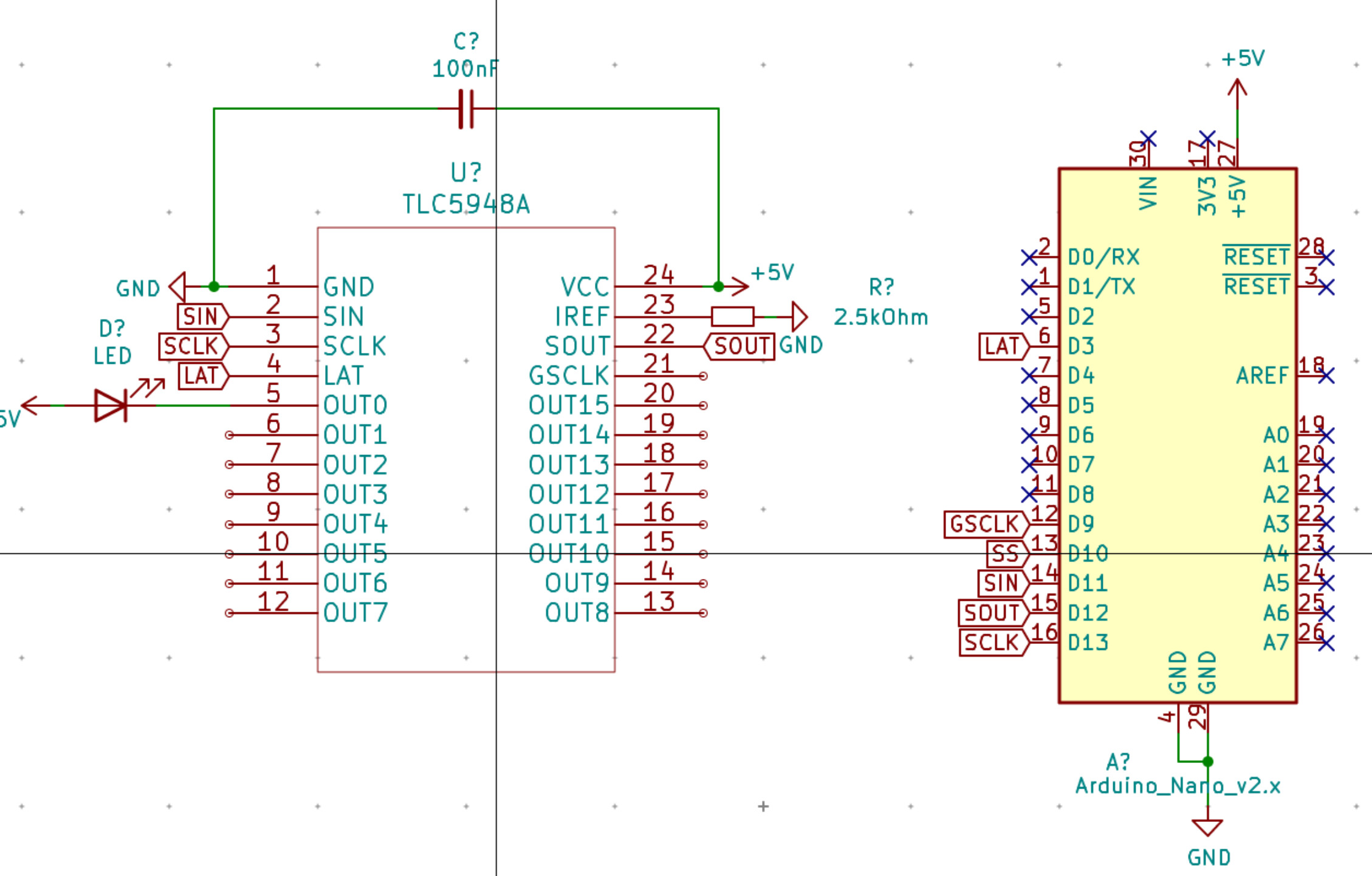
Background/Setup:
I'm using the TLC5948A chip by TI. In my I have implemented on a breadboard. Basically, I have the IC on a SSOP24 breakout board which is wired with its SPI interface to an Arduino Nano (SIN->MOSI; SOUT->MISO; SCLK->SCLK). It includes a 100nF THT capacitor on the breadboard, as well as 2 THT resistors that make up the 2.5kOhm resistor in the schematic. I'm not sure if using a THT components could be problematic for a testing rig like this. I'm also using one THT LED that I move between outputs to check each channel (due to Arduino power draw limits). I've tried using separate as well as a single power supply to power the LED and the IC, with no discernible difference in the output.
Overview of the TLC5948:
The TLC5948 is a 16-channel LED Driver. It contains a 257 (256 data bits and 1 register select bit) register that shifts in data from SIN and out of SOUT. If the 257th bit (MSB) is 1 when the LAT rises, the data is latched into a control register. If it's a 0, then the data is latched into a grayscale (GS) register. There is a bit more nuance to when the values in the registers are actually used by the PWM hardware, but since I'm just doing a sanity check and writing the values once on startup, they should be latched where they need to be (see the notes on the BLANK bit in the sheet, page 28/29 under first+second GS and function control data latches). The basic idea: I make a 32-byte array, populate it as specified in the datasheet for GS data, manually shift in a register select bit (257th bit) and then SPI.transfer the array. I rinse and repeat for the control data. As far as I know, hardware SPI is acceptable for this application, but maybe not? Can someone confirm or deny this?
Problem:
No matter what grayscale, dot correction or brightness control values I feed it with my library, several LEDs randomly turn on, and then turn off after one write of GS data. They also flash after writing the control data to it. The strangest behavior I've noticed is the LEDs being ON even before a 3 second delay prior to writing anything to it. According to the datasheet, nothing should be on in that case (the BLANK bit is always '1' on startup, which is supposed to force all outputs off until it's set to 0...). I'm really scratching my head as to what could be the cause.
Things I've tried/checked:
- Setting the SPI speed really slow (10Khz currently)
- Checking for shorts/issues/frying with the IC -multiple chips produce the same response
- Checking that I didn't fry my Arduino somehow - SPI still works across two Arduino boards
- Checking MSBFIRST setting
- Writing the data with the most significant byte at index 0 (this is currently how I do it)
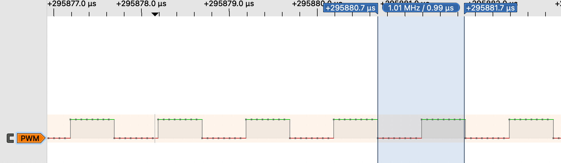
- Adjusting the PWM speed (I started with the default 490Hz on Pin D9, now its 31Khz) for GSCLK
- Looking at the TI example software. Maybe a stronger woman/man than I can decipher what's going on in that code but honestly it's a massive headache to look at and seems to be doing what I'm doing as far as I can tell, though with a bit-bang'ed SPI. There is a strange use of __delay_cycles(6) to achieve a 240ns delay at points... I couldn't find anything in the datasheet pertinent to that. I tried to achieve similar effect but by using 4 nops ~ 250ns, if my math is right. Still no effect on the output.
If you made it this far, thank you for taking the time and (if you're willing) maybe we can figure this out together : ) (and most likely laugh about something stupid I've done)!


