LCD comes with header not soldered to it, so I soldered it myself. I not too good in soldering for now, but I've checked with multimeter that pins are not short and that the wires I use on a breadboard are not broken. I have checked +5V and GND lines from pins on the screen to pins on Arduino
Backlight works, I just ommited it from the photo
What I get: just blank screen, nothing on it. Contrast does nothing. One time I saw random symbols.
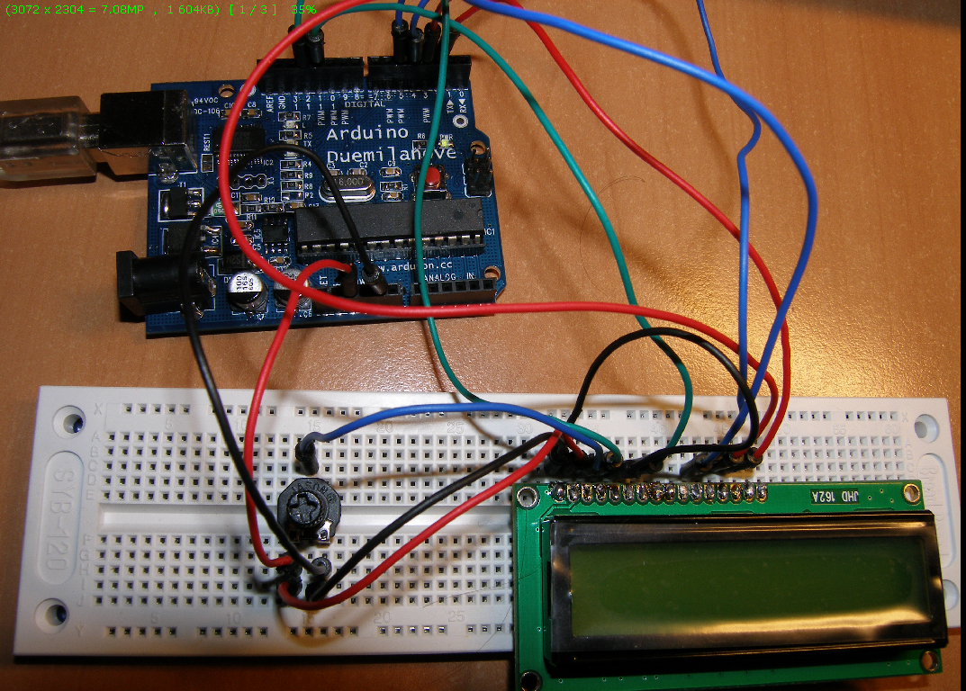
Photo of the wiring:
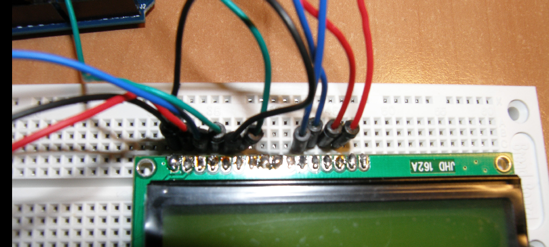
closer:
Some questions:
Is any simple procedure to test LCD (even without Arduino) if it is still alive?
Can the screen be damaged with continuity test mode on multimeter?
I've repeated everything from scratch with LiquidCrystal library and get nothing when arduino is running the sketch. But if I disconnect screen WITHOUT resetting Arduino (while it is still powered) and put it back it begin to show random characters. When I press arduino's reset after that screen shows stripe running from left to right and again blank screen.
I also have checked all my Arduino digital pins by blinking led on them -- they all seems to work.
Can it be a problem with inialization or hardware failure?
We need to see the actual code that you used so we can compare it to the wiring in your photo. We also have to be able to unambiguously follow each wire all the way from the LCD to the Arduino.
The LCD4bit library referenced in this link does not properly initialize the LCD controller.
Can it be a problem with inialization or hardware failure?
Most likely initialization.
I suggest that you remove all of your wires and then start again using the tutorial at Arduino Tutorial - connecting a parallel LCD. Don't skip any of the steps and if you don't get the single row of blocks (about halfway through the tutorial) then there's no sense going any further.
Is any simple procedure to test LCD (even without Arduino) if it is still alive?
If you get those blocks then there's a good chance that your LCD is OK. At this point you haven't used the Arduino yet.
// include the library code:
#include <LiquidCrystal.h>

// initialize the library with the numbers of the interface pins
LiquidCrystal lcd(12, 11, 5, 4, 3, 2);

void setup() {
  // set up the LCD's number of columns and rows:
  lcd.begin(16, 2);
  // Print a message to the LCD.
  lcd.print("hello, world!");
}

void loop() {
  // set the cursor to column 0, line 1
  // (note: line 1 is the second row, since counting begins with 0):
  lcd.setCursor(0, 1);
  // print the number of seconds since reset:
  lcd.print(millis()/1000);
}
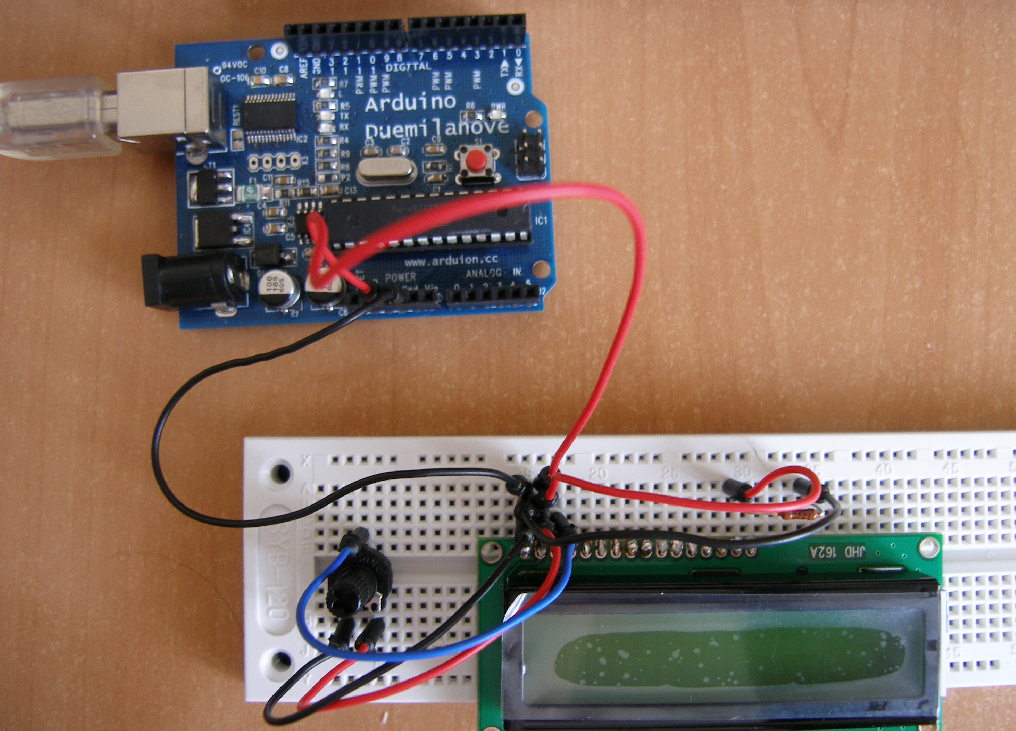
I don't see any rectangles (just blank screen with backlight on) after connecting power to logic, backlight and contrast. Here is a picture with minimal wiring:
I just add resistor for backlight (isn't this a mistake that it is ommited in the tutorial?)
I just add resistor for backlight (isn't this a mistake that it is ommited in the tutorial?)
Some LCD modules have the resistor on the pc board and some require an external resistor. It certainly won't hurt to have an external resistor even if there is one on the board as long as the backlight is bright enough.
Well you have to get the blocks showing before you go any further. I assume that the backlight works and that the module doesn't get hot. I also assume that you have turned the pot from one end to the other as mentioned in the tutorial.
The potentiometer could be bad. If you have another one then you should try it. Almost any pot should work for testing purposes although the recommended value is 10K. Some LCD modules work reasonably well with pin 3 connected to GND so you could try that as well.
There are some 'extended temperature' LCD modules that require a negative voltage on pin 3 so that is another possibility. I don't know if there is such a variant for the JHD162A. To check this out you need another power supply, a 9v battery will do. Disconnect the black potentiometer lead from pin 1 and connect that wire to the negative side of your second power supply. Connect the positive side of that new supply to GND.
Thank you for helping me! I'd like to provide as detail description as I can.
Some LCD modules have the resistor on the pc board and some require an external resistor. It certainly won't hurt to have an external resistor even if there is one on the board as long as the backlight is bright enough.
My screen has resistor on backlight (I see it on the back side), but even with my 500K resistor backlight is bright.
I assume that the backlight works and that the module doesn't get hot.
I haven't touched chips on the back side (LCD is on a breadboard). What should I check?
I also assume that you have turned the pot from one end to the other as mentioned in the tutorial.The potentiometer could be bad. If you have another one then you should try it.
The pot is working, I checked it with multimeter (0 Ohm in one position 10 Ohm in other). And I can get random characters on display by unpluging and pluging it back to Arduino without plugging power back, so I assume that contrast works.
There are some 'extended temperature' LCD modules that require a negative voltage on pin 3 so that is another possibility.
If I can characters the procedure I described, can I assume that contrast is ok?
What can I check, may be my soldering is bad? I have checked with continuity test on multimeter, but may be there is something I missed?
The pot is working, I checked it with multimeter (0 Ohm in one position 10 Ohm in other).
If you are really using a 10 Ohm instead of 10K Ohm !0,000 Ohm) potentiometer then this may be the source of your problem. This alone will draw 500 mA which is the limit of the USB 5v supply. If it really is 10 Ohms then try removing the pot and grounding pin 3 and see what you get. Otherwise use your multimeter to verify that you can adjust the pin 3 voltage between 0 and 5 V.
I plugged 12V supply in addition to USB cord and now example works. But I don't understand why it doesn't work from USB? I've tried my notebook USB port and external powered hub -- it gives 3.5V and screen doesn't work. With external power supply it works...
I've tried my notebook USB port and external powered hub -- it gives 3.5V ....
Although the 328 can run at a lower voltage, the Arduino is configured to run it at 5 volts. The LCD module is probably also designed to run at 5 volts although there are some that run at a lower voltage.
Quote:
The Arduino Duemilanove can be powered via the USB connection or with an external power supply. The power source is selected automatically.
Is this a error and it always need external supply to work realible. Or my board is broken?
The automatic power selection switches from the USB supply to the external supply whenever the external supply is more than approximately 7.3 Volts. Here's a diagram that I drew to figure out how it worked when the Duemilanove first came out. If you want a pdf version then copy the 'image location' and substitute pdf for gif. The UNO is somewhat different but the principle is the same.
It looks like your netbook USB port is not supplying 5 V.