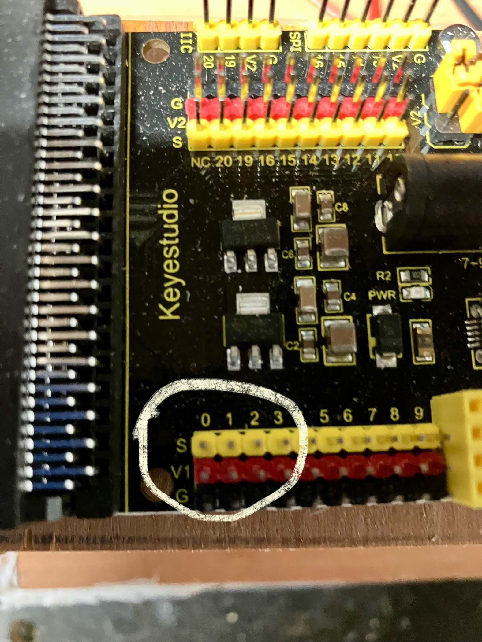
Hi I have a keystudio expansion card connected to my microbit V2 card and I am connected that to the Arduino uno The Arduino will have 12v from fusebox via jack plug
Microsoft copilot says connect S0 to A0, S1 to A1, G to GND and V1 to the 5v on Arduino
Just want to make sure it’s correct as copilot has made some errors
Thanks anyone that can confirm this is ok
Disclaimer: I'm not familiar with the MicroBit nor with the expansion shield; I also could not find which expansion shield that exactly is and its schematic.
The MicroBit V2 uses (seems to use) the NXP MKL27Z256VFM4 processor which is a 3.3V processor. The Uno is a 5V processor.
If you want to send output signals from the MicroBit to the Uno that is OK. If you want to send output signals from the Uno to the MicroBit you run the risk of damaging the MicroBit and you need level converters; maybe they are implemented on the expansion board?
S will be the signal pin on the expansion board.
G will be ground.
You will usually use V1 to power the connected device (the Uno in this case). So you might not need that connection.
The only advice: be careful.
This is the schematic of the MicroBit that I found: MicroBit_V2.0.0_S_schematic.PDF (1.6 MB). Source: GitHub - microbit-foundation/microbit-v2-hardware: The schematic and Bill of Material for the BBC micro:bit V2.
This is the "specification" of the expansion connector

There is no 5V on the expansion connector !!
If you provide the schematic of the exact expansion board that you're using people can look further into it.

It’s a bit of a struggle for me as I’m a mechanical man
I built K9 dr who full size and to motorise it wireless joystick controls has been difficult to get my head around sometimes
A joystick can be made of two independent, variable resistors (for example) which form independent voltage dividers translating the relative position (0vdc to VCC) of the joystick in the "x" and "y" potentiometer, each being fed to two, independent ADC (analog to digital converter) channels which create the digital equivalent of the two analog inputs/joystick positions. These two digital values can be used together, of independently.
Some joysticks have auto-return-to-center mechanisms, while some do not. Some use Hall Effect transistors rather than potentiometers.
Thank you for your reply