Is it possible to use a 9v battery???
Would that be easier or harder???
Also the thought of the hall sensor would be cool...
Thanks
Michael
A 9V battery would be easy enough while using the Nano. It has a built-in regulator. You would connect the battery to the Vin/RAW. Battery life will not be very good. 9V batteries do not have a large capacity, and the regulator will waste four ninths of that energy. With AA/AAA cells, you would bypass the regulator by connecting them to the Vcc/5V pin. Its important not to exceed 5.5V when bypassing the regulator, or the Arduino could be damaged. For example 4 non-rechargeable AA/AAA would be 6V, too much, whereas 4 rechargeable would be less than 5.5V even when freshly charged.
Using the tiny85 would be more difficult with a 9V battery. You would have to add a regulator to your circuit. This could be as simple as a 78L05 regulator (3 pins) and a couple of caps. But, as mentioned, four ninths of the battery's energy gets wasted.
I just want you to check this out before I hook it up...
Thanks
Michael
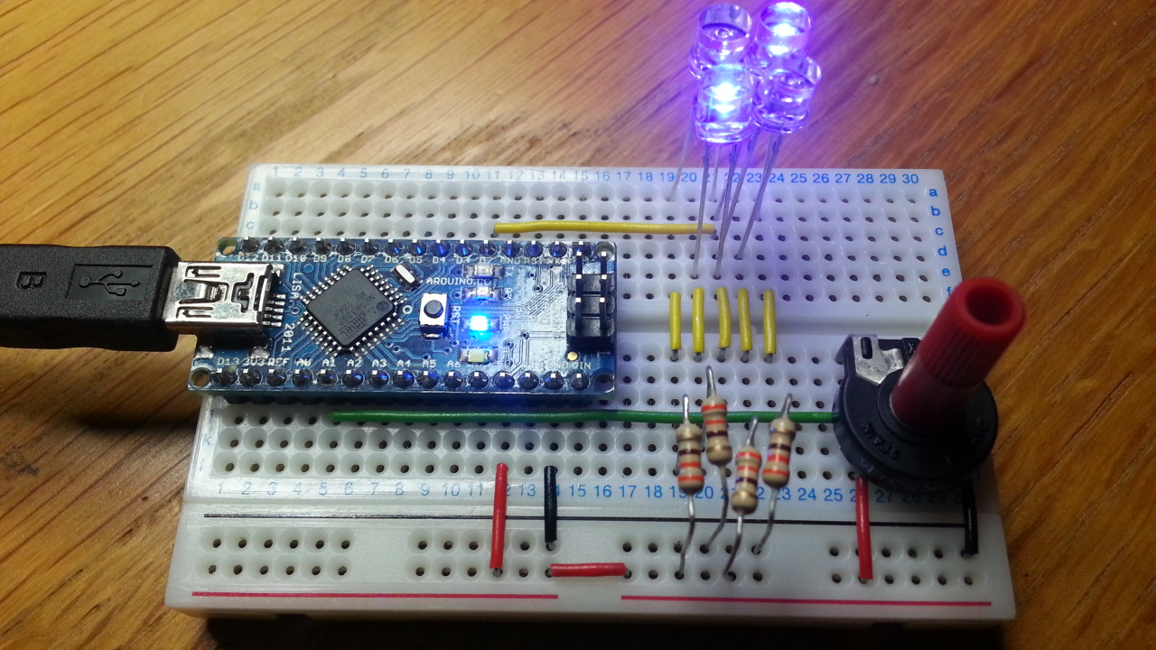
Sorry Michael, from that angle and with all those flying leads, I can't really tell what's connected to what. If you use short straight leads flat to the breadboard and take the picture from directly above, I might have a chance.
Having said that, looking at the 2 leds nearest the camera, I think it looks right as far as I can tell. If the other 2 are the same, you should be reasonably safe to connect up.
Here's an example of how I like to work on breadboard. Its a much more complicated circuit but I hope you get what I mean.
http://forum.arduino.cc/index.php?topic=188135.msg1392372#msg1392372
Have you got the Arduino software installed yet and uploaded a sketch? You shold be able to use the "blink" sketch from the examples menu to test your 4 leds. Just change the pin number in the sketch to match the one you have connected on the breadboard.
Here is some more pic's...
Hope these help...
Thanks
Michael
That was more than enough pics!
Ok, the leds look ok. The power connections from the Nano need fixing. Use the 5V pin, not Vin. Use the GND pin on that same side of the Nano, or if you prefer, both GND pins. Have another look at my pic on that link.
The common practice is to use black wire for GND, red for +V, and other colours for other signals.
Can you help me out with the sketch???
I don't know how to even start one...
Thanks
Michael
Like I said before:
PaulRB:
You shold be able to use the "blink" sketch from the examples menu to test your 4 leds. Just change the pin number in the sketch to match the one you have connected on the breadboard.
OK I got it up and running...
I have 1 problem tho...
I hooked everything up to your diagram but I couldn't get it to run only the first LED would only light up so
I had to use 2 Pins D3 and D4...
I have 2 sketch's that will run now Slow and Fast...
Here is the links...
Slow
Fast
Here is a pic of the new layout...
Thanks
Michael
Good work Michael!
But it should have worked fine with just one digital pin. If I get time later I will set it up on my breadboard to show you. You do know leds only work if plugged in the right way around?
What next? Do you have a pot (potentiometer/trimmer/variable resistor)? You could wire that up to an analog input as a temporary replacement for the hall sensor/thermistor and use it to vary the flashing speed.
Why are we using an Arduino to do the job of a NE555?
:~
Paul__B:
Why are we using an Arduino to do the job of a NE555?:~
Michael wants some beep tones, some fading leds and a thermistor, hall sensor or something. This is just the first step. The plan is to use a tiny85 for the final version.
Michael, how about one of these hall sensors:
They should be easy to use, just connect the leads to 0V, 5V and an analog input on the Arduino. The reading from analogRead() should be around 512 when no magnetic field is present, but will rise above that or fall below it when north or south poles of magnets are detected.
Hi Michael, here is the circuit with the 4 leds using only one Arduino pin:
And next with a pot to control the speed:

Paul what sketch did you use for that???
Thanks
Michael
Is there a way to have it blink at one rate for so long then blink at another rate for so long in the same sketch???
Thanks
Michael
jameskirk:
Paul what sketch did you use for that???
This is just the "blink" example sketch with a couple of adjustments:
/*
  Blink
 Turns on an LED on for one second, then off for one second, repeatedly.

 This example code is in the public domain.
 */

// Pin 13 has an LED connected on most Arduino boards.
// give it a name:
int led = 2;

// the setup routine runs once when you press reset:
void setup() {
  // initialize the digital pin as an output.
  pinMode(led, OUTPUT);
}

// the loop routine runs over and over again forever:
void loop() {
  int d = analogRead(A1);
  digitalWrite(led, HIGH);   // turn the LED on (HIGH is the voltage level)
  delay(d);               // wait for a second
  digitalWrite(led, LOW);    // turn the LED off by making the voltage LOW
  delay(d);               // wait for a second
}
jameskirk:
Is there a way to have it blink at one rate for so long then blink at another rate for so long in the same sketch???
Yes, all perfectly do-able.
jameskirk:
Is there a way to have it blink at one rate for so long then blink at another rate for so long in the same sketch???
Thanks
Michael
Hey, we are dealing with a microprocessor here, it's no slouch.
If you program it to do so, it can do hundreds of different patterns before breakfast. ![]()
The reason I ask this is we wouldn't need a pot to adjust the lights if
we can have it speed up after a certain amount of time...
Can we still use the Piezo speaker to make sound for it???
Thanks
Michael