Hi everyone,
I'm facing a very specific and frustrating issue trying to get a standard L293D Motor Shield (an Adafruit V1 clone) to work with a Keyestudio ESP32 PLUS board. I'm hoping someone in the community has encountered this and can offer a solution.
Goal
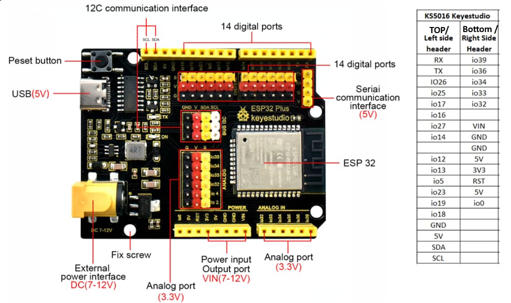
My goal is to reliably control all four DC motor channels (M1, M2, M3, M4) on the L293D Motor Shield using a Keyestudio ESP32 PLUS board, which has an Arduino Uno R3 layout.
Problem Statement
When I run a test script to sequence through all four motors, only motors M1 and M2 work correctly. Motors M3 and M4 do not run at all.
The most critical piece of information is this: The exact same shield, with the exact same motors and power supply, works perfectly when placed on an Arduino Uno board. This confirms that the shield, the L293D ICs, and the motors are all fully functional. The problem only occurs when using the ESP32.
Hardware Setup
-
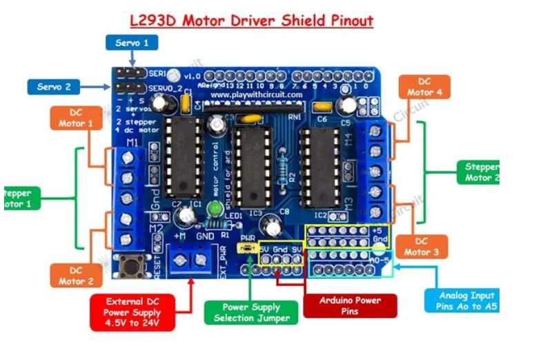
Shield: L293D Motor Drive Expansion Shield (Adafruit V1 Clone)
-
Power: 12V DC power adapter connected to the ESP32's DC jack, with the power jumper ON on the shield. (I have also tried powering the shield via the
EXT_PWRblock with the jumper off, with no change in results).
Troubleshooting Steps Taken
We have gone through an exhaustive debugging process to isolate the issue:
-
Verified Pin Mappings: We confirmed the correct mapping between the shield's "D" pins and the ESP32's GPIOs.
-
Custom Library-Free Code: We wrote our own control code from scratch to directly manipulate the shield's 74HC595 shift register and PWM pins, removing any potential library conflicts.
-
Corrected Motor Bit Mapping: We analyzed the original
AFMotor.cpplibrary to ensure our code uses the official bit mapping for the shift register (M1={2,3},M2={1,4},M3={5,7},M4={0,6}). -
State Management: We tested multiple ways of managing the
latch_statevariable, including clearing all bits before each command and only clearing the specific bits for the target motor. -
Signal Timing: We replaced the standard
shiftOut()function with a slower, manual version with microsecond delays to rule out any signal timing issues between the fast ESP32 and the older shield. -
Hardware Swapping:
-
We physically swapped the two L293D ICs on the shield. The problem remained on M3/M4.
-
We physically swapped the DC motors. The problem remained on the M3/M4 channels.
-
-
Isolated Motor Tests: We created minimal test scripts to run only Motor 3 and only Motor 4. In these isolated tests, both motors run forward and backward correctly. The failure only occurs when running the full 4-motor test sequence.
The Core Question for the Community
Given that the shield works perfectly with a 5V Arduino Uno but fails on the 3.3V ESP32 (specifically on the M3/M4 channels controlled by the 74HC595 shift register), has anyone else experienced this?
Is this a known 3.3V vs. 5V logic level incompatibility with this specific shield's shift register? And if so, has anyone found a solution that does not require an external logic level shifter?
Test Code
Here is the final, clean test code we are using. It includes all the correct pin mappings and control logic that we've confirmed through debugging.
all 4 motors successfully runs on an Arduino Uno(with simple code with AFMotor.h) and its confirmed the shield is working properly but fails on M3/M4 with the ESP32 with below code.
/*
 * 4-Motor Test for ESP32 + L293D Shield
 * ----------------------------------------------------
 * This script is designed to test all four motor channels.
 * It uses the official pin mappings and motor bit assignments for the
 * Adafruit V1 shield, but M3 and M4 fail to run on an ESP32.
 */

// --- Pin Definitions for Keyestudio ESP32 PLUS (KS5016) ---
const int MOTOR_LATCH = 19; // Shield pin D12 -> ESP32 GPIO 19
const int MOTOR_DATA = 12;  // Shield pin D8  -> ESP32 GPIO 12
const int MOTOR_CLK = 17;   // Shield pin D4  -> ESP32 GPIO 17
const int MOTOR_ENABLE = 14;// Shield pin D7  -> ESP32 GPIO 14
const bool ENABLE_ACTIVE_STATE = LOW;

// PWM (Speed Control) Pins for all motors
const int M1_PWM_PIN = 23; // Shield pin D11 -> ESP32 GPIO 23
const int M2_PWM_PIN = 25; // Shield pin D3  -> ESP32 GPIO 25
const int M3_PWM_PIN = 16; // Shield pin D5  -> ESP32 GPIO 16
const int M4_PWM_PIN = 27; // Shield pin D6  -> ESP32 GPIO 27

// --- ESP32 PWM Configuration ---
const int PWM_FREQ = 2000;
const int PWM_RESOLUTION = 8;

// --- Motor Configuration ---
#define MOTOR_TEST_SPEED 200 // Set motor speed for the test (0-255)
#define FORWARD 1
#define BACKWARD 2
#define RELEASE 4

// Official bit mapping from AFMotor.cpp
const uint8_t MOTOR_BITS[4][2] = {
  {2, 3}, // Motor 1
  {1, 4}, // Motor 2
  {5, 7}, // Motor 3
  {0, 6}  // Motor 4
};

static uint8_t latch_state = 0;

// --- Core Motor Functions ---
void updateShiftRegister() {
  digitalWrite(MOTOR_LATCH, LOW);
  // Manual shiftOut for signal stability
  for (uint8_t i = 0; i < 8; i++)  {
      digitalWrite(MOTOR_DATA, !!(latch_state & (1 << (7 - i))));
      digitalWrite(MOTOR_CLK, HIGH);
      delayMicroseconds(10);
      digitalWrite(MOTOR_CLK, LOW);
      delayMicroseconds(10);
  }
  digitalWrite(MOTOR_LATCH, HIGH);
}

void setMotorSpeed(int motorNum, int speed) {
  if (motorNum < 1 || motorNum > 4) return;
  if (speed < 0) speed = 0; if (speed > 255) speed = 255;
  switch (motorNum) {
    case 1: ledcWrite(M1_PWM_PIN, speed); break;
    case 2: ledcWrite(M2_PWM_PIN, speed); break;
    case 3: ledcWrite(M3_PWM_PIN, speed); break;
    case 4: ledcWrite(M4_PWM_PIN, speed); break;
  }
}

void setMotorDirection(int motorNum, uint8_t direction) {
  if (motorNum < 1 || motorNum > 4) return;
  uint8_t inA_bit = MOTOR_BITS[motorNum - 1][0];
  uint8_t inB_bit = MOTOR_BITS[motorNum - 1][1];

  // Targeted Bit Clear: Clears only the bits for the current motor
  latch_state &= ~_BV(inA_bit);
  latch_state &= ~_BV(inB_bit);

  // Set the new direction
  switch (direction) {
    case FORWARD:
      latch_state |= _BV(inA_bit);
      break;
    case BACKWARD:
      latch_state |= _BV(inB_bit);
      break;
    case RELEASE:
      break;
  }
  updateShiftRegister();
}

// --- Arduino Setup ---
void setup() {
  Serial.begin(115200);
  Serial.println("--- 4-Motor Test for ESP32 ---");

  pinMode(MOTOR_LATCH, OUTPUT);
  pinMode(MOTOR_CLK, OUTPUT);
  pinMode(MOTOR_DATA, OUTPUT);
  pinMode(MOTOR_ENABLE, OUTPUT);
  digitalWrite(MOTOR_ENABLE, ENABLE_ACTIVE_STATE);

  ledcAttach(M1_PWM_PIN, PWM_FREQ, PWM_RESOLUTION);
  ledcAttach(M2_PWM_PIN, PWM_FREQ, PWM_RESOLUTION);
  ledcAttach(M3_PWM_PIN, PWM_FREQ, PWM_RESOLUTION);
  ledcAttach(M4_PWM_PIN, PWM_FREQ, PWM_RESOLUTION);

  for (int i = 1; i <= 4; i++) {
    setMotorDirection(i, RELEASE);
    setMotorSpeed(i, 0);
  }
  Serial.println("Setup complete. Starting test loop.");
}

// --- Main Loop ---
void loop() {
  for (int i = 1; i <= 4; i++) {
    Serial.printf("\n--- Testing Motor %d ---\n", i);
    setMotorDirection(i, FORWARD);
    setMotorSpeed(i, MOTOR_TEST_SPEED);
    delay(2000);

    setMotorDirection(i, RELEASE);
    setMotorSpeed(i, 0);
    delay(2000);

    setMotorDirection(i, BACKWARD);
    setMotorSpeed(i, MOTOR_TEST_SPEED);
    delay(2000);

    setMotorDirection(i, RELEASE);
    setMotorSpeed(i, 0);
    delay(2000);
  }
}